Netgear GSM7224 GSM7224 User Manual - Page 35
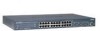
Quick Startup Physical Port Data, Quick Startup User Account Management - 24 port layer 2 managed gigabit switch
 |
UPC - 606449069150
View all Netgear GSM7224 manuals
Add to My Manuals
Save this manual to your list of manuals |
Page 35 highlights
User Manual for the NETGEAR 7200 Series Layer 2 Managed Switch Software Quick Startup Physical Port Data Table 6-2. Quick Startup Physical Port Data Command show port all Details Displays the Port Characteristics Slot.Port - slot number.port number Slot Options: 0 - the port is one of the physical ports 1 - a link aggregation group (LAG). The port number field in this case refers to the LAG group ID. 3 - a VLAN group. The port field starts with 1 as the first VLAN group created in the switch. Port (when Slot value is 0): Ports 1-24 are gigabit copper ports, ports 21-24 can also be used as fiber ports Type - indicates if the port is a special type of port STP State - displays the Spanning Tree status Admin Mode - selects the Port Control Administration State Physical Mode - selects the desired port speed and duplex mode Physical Status - indicates the port speed and duplex mode Link Status - indicates whether the link is up or down Link Trap - determines whether or not to send a trap when link status changes LACP Mode - displays whether LACP is enabled or disabled on this port. Quick Startup User Account Management Table 6-3. Quick Startup User Account Management Command Details show users Displays all of the users that are allowed to access the switch Access Mode - Shows whether the user is able to change parameters on the switch (Read/Write) or is only able to view then (Read Only). As a factory default, admin has Read/Write access and guest has Read Only access. There can only be one Read/Write user and up to 5 Read Only users. Quick Startup 6-3 202-10010-01
-
 1
1 -
2
-
3
-
4
-
5
-
6
-
7
-
8
-
9
-
10
-
11
-
12
-
13
-
14
-
15
-
16
-
17
-
18
-
19
-
20
-
21
-
22
-
23
-
24
-
25
-
26
-
27
-
28
-
29
-
 30
30 -
 31
31 -
 32
32 -
 33
33 -
 34
34 -
 35
35 -
 36
36 -
 37
37 -
 38
38 -
 39
39 -
 40
40 -
41
-
42
-
43
-
44
-
45
-
46
-
47
-
48
-
49
-
50
-
51
-
52
-
53
-
54
-
55
-
56
-
57
-
58
-
59
-
60
-
61
-
62
-
63
-
64
-
65
-
66
-
67
-
68
-
69
-
70
-
71
-
72
-
73
-
74
-
75
-
76
-
77
-
78
-
79
-
80
-
81
-
82
-
83
-
84
-
85
-
86
-
87
-
88
-
89
-
90
-
91
-
92
-
93
-
94
-
95
-
96
-
97
-
98
-
99
-
100
-
101
-
102
-
103
-
104
-
105
-
106
-
107
-
108
-
109
-
110
-
111
-
112
-
113
-
114
-
115
-
116
-
117
-
118
-
119
-
120
-
121
-
122
-
123
-
124
-
125
-
126
-
127
-
128
-
129
-
130
-
131
-
132
-
133
-
134
-
135
-
136
-
137
-
138
-
139
-
140
-
141
-
142
-
143
-
144
-
145
-
146
-
147
-
148
-
149
-
150
-
151
-
152
-
153
-
154
-
155
-
156
-
157
-
158
 |
 |
