Netgear WB7530 User Manual - Page 26
Wireless Controller System Components
 |
View all Netgear WB7530 manuals
Add to My Manuals
Save this manual to your list of manuals |
Page 26 highlights
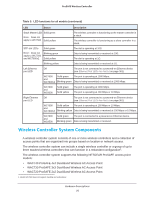
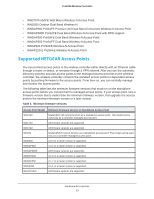
ProSAFE Wireless Controller Table 5. LED functions for all models (continued) LED Status Description Stack Master LED Solid green Note: Does not apply to WC7500 Solid yellow The wireless controller is functioning as the master controller in a stack. The wireless controller is functioning as a slave controller in a stack. SFP slot LEDs Solid green Note: Does not Blinking green apply to WC7500 and WC7600v2 Solid yellow The slot is operating at 10G. Data is being transmitted or received at 10G. The slot is operating at 1G. Blinking yellow Data is being transmitted or received at 1G. Left Ethernet Off port LED The port is not connected to a powered-on Ethernet device (see Ethernet Port LEDs Are Not Lit on page 361). WC7500 Solid green The port is operating at 1000 Mbps. and WC7600v2 Blinking green Data is being transmitted or received at 1000 Mbps. WC7600 and WC9500 Solid green Solid yellow The port is operating at 1000 Mbps. The port is operating at 100 Mbps or 10 Mbps. Right Ethernet Off port LED The port is not connected to a powered-on Ethernet device (see Ethernet Port LEDs Are Not Lit on page 361). WC7500 Solid yellow The port is operating at 100 Mbps or 10 Mbps. and WC7600v2 Blinking yellow Data is being transmitted or received at 100 Mbps or 10 Mbps. WC7600 and WC9500 Solid green The port is connected to a powered-on Ethernet device. Blinking green Data is being transmitted or received. Wireless Controller System Components A wireless controller system consists of one or more wireless controllers and a collection of access points that are organized into groups based on location or network access. The wireless controller system can include a single wireless controller or a group of up to three stacked wireless controllers that can function in a redundant configuration1. The wireless controller system supports the following NETGEAR ProSAFE access point models: • WAC740 ProSAFE 4x4 Dual-Band Wireless AC Access Point • WAC730 ProSAFE 3x3 Dual-Band Wireless AC Access Point • WAC720 ProSAFE 2x2 Dual-Band Wireless AC Access Point 1. Model WC7500 does not support stacking and redundancy. Hardware Descriptions 26
-
 1
1 -
2
-
3
-
4
-
5
-
6
-
7
-
8
-
9
-
10
-
11
-
12
-
13
-
14
-
15
-
16
-
17
-
18
-
19
-
20
-
 21
21 -
 22
22 -
 23
23 -
 24
24 -
 25
25 -
 26
26 -
 27
27 -
 28
28 -
 29
29 -
 30
30 -
 31
31 -
32
-
33
-
34
-
35
-
36
-
37
-
38
-
39
-
40
-
41
-
42
-
43
-
44
-
45
-
46
-
47
-
48
-
49
-
50
-
51
-
52
-
53
-
54
-
55
-
56
-
57
-
58
-
59
-
60
-
61
-
62
-
63
-
64
-
65
-
66
-
67
-
68
-
69
-
70
-
71
-
72
-
73
-
74
-
75
-
76
-
77
-
78
-
79
-
80
-
81
-
82
-
83
-
84
-
85
-
86
-
87
-
88
-
89
-
90
-
91
-
92
-
93
-
94
-
95
-
96
-
97
-
98
-
99
-
100
-
101
-
102
-
103
-
104
-
105
-
106
-
107
-
108
-
109
-
110
-
111
-
112
-
113
-
114
-
115
-
116
-
117
-
118
-
119
-
120
-
121
-
122
-
123
-
124
-
125
-
126
-
127
-
128
-
129
-
130
-
131
-
132
-
133
-
134
-
135
-
136
-
137
-
138
-
139
-
140
-
141
-
142
-
143
-
144
-
145
-
146
-
147
-
148
-
149
-
150
-
151
-
152
-
153
-
154
-
155
-
156
-
157
-
158
-
159
-
160
-
161
-
162
-
163
-
164
-
165
-
166
-
167
-
168
-
169
-
170
-
171
-
172
-
173
-
174
-
175
-
176
-
177
-
178
-
179
-
180
-
181
-
182
-
183
-
184
-
185
-
186
-
187
-
188
-
189
-
190
-
191
-
192
-
193
-
194
-
195
-
196
-
197
-
198
-
199
-
200
-
201
-
202
-
203
-
204
-
205
-
206
-
207
-
208
-
209
-
210
-
211
-
212
-
213
-
214
-
215
-
216
-
217
-
218
-
219
-
220
-
221
-
222
-
223
-
224
-
225
-
226
-
227
-
228
-
229
-
230
-
231
-
232
-
233
-
234
-
235
-
236
-
237
-
238
-
239
-
240
-
241
-
242
-
243
-
244
-
245
-
246
-
247
-
248
-
249
-
250
-
251
-
252
-
253
-
254
-
255
-
256
-
257
-
258
-
259
-
260
-
261
-
262
-
263
-
264
-
265
-
266
-
267
-
268
-
269
-
270
-
271
-
272
-
273
-
274
-
275
-
276
-
277
-
278
-
279
-
280
-
281
-
282
-
283
-
284
-
285
-
286
-
287
-
288
-
289
-
290
-
291
-
292
-
293
-
294
-
295
-
296
-
297
-
298
-
299
-
300
-
301
-
302
-
303
-
304
-
305
-
306
-
307
-
308
-
309
-
310
-
311
-
312
-
313
-
314
-
315
-
316
-
317
-
318
-
319
-
320
-
321
-
322
-
323
-
324
-
325
-
326
-
327
-
328
-
329
-
330
-
331
-
332
-
333
-
334
-
335
-
336
-
337
-
338
-
339
-
340
-
341
-
342
-
343
-
344
-
345
-
346
-
347
-
348
-
349
-
350
-
351
-
352
-
353
-
354
-
355
-
356
-
357
-
358
-
359
-
360
-
361
-
362
-
363
-
364
-
365
-
366
-
367
-
368
-
369
-
370
-
371
-
372
-
373
-
374
-
375
-
376
-
377
-
378
-
379
-
380
-
381
-
382
-
383
-
384
-
385
-
386
-
387
-
388
-
389
-
390
-
391
-
392
-
393
-
394
-
395
-
396
-
397
-
398
 |
 |