NordicTrack Cx 925 Elliptical English Manual - Page 4
Assembly
 |
View all NordicTrack Cx 925 Elliptical manuals
Add to My Manuals
Save this manual to your list of manuals |
Page 4 highlights
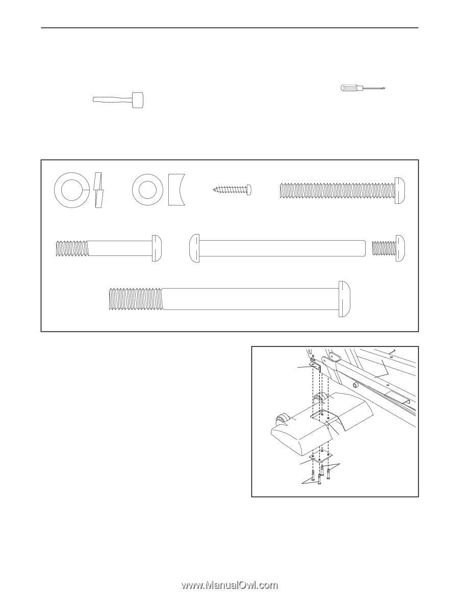
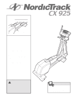
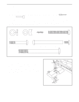
ASSEMBLY Assembly requires two persons. Place all parts of the elliptical exerciser in a cleared area and remove the packing materials. Do not dispose of the packing materials until assembly is completed. Assembly requires the included allen wrenches and your own phillips screwdriver and rubber mallet . As you assemble the elliptical exerciser, use the drawings below to identify the small parts used in assembly. The number in parentheses below each drawing refers to the key number of the part, from the PART LIST on page 21. The second number refers to the quantity used in assembly. Note: Some small parts may have been pre-assembled. If a part is not in the parts bag, check to see if it is pre-assembled. M10 Split Washer (73)-2 7.6mm Spacer (47)-2 M4 x 16mm Screw (94)-4 M8 x 54mm Button Screw (83)-4 M8 x 44mm Button Screw (84)-8 M8 x 79mm Bolt Set (65)-2 M10 x 108mm Button Screw (70)-2 1. Identify the Front Stabilizer (8). While another person lifts the front of the Frame (1) and holds the Pedal 1 Legs (4, 5) in the position shown, attach the Front 1 Stabilizer to the Frame with four M8 x 44mm Button 4, 5 Screws (84) and a Support Plate (64). While another person lifts the rear of the Frame (1), attach the Rear Stabilizer (not shown) to the Frame in the same way. 8 64 84 84 4
-
 1
1 -
 2
2 -
 3
3 -
 4
4 -
 5
5 -
 6
6 -
 7
7 -
 8
8 -
 9
9 -
 10
10 -
11
-
12
-
13
-
14
-
15
-
16
-
17
-
18
-
19
-
20
-
21
-
22
-
23
-
24
 |
 |