NordicTrack Cx 925 Elliptical English Manual - Page 6
wire on the Console. Connect the Upper Wire Harness - battery cover
 |
View all NordicTrack Cx 925 Elliptical manuals
Add to My Manuals
Save this manual to your list of manuals |
Page 6 highlights
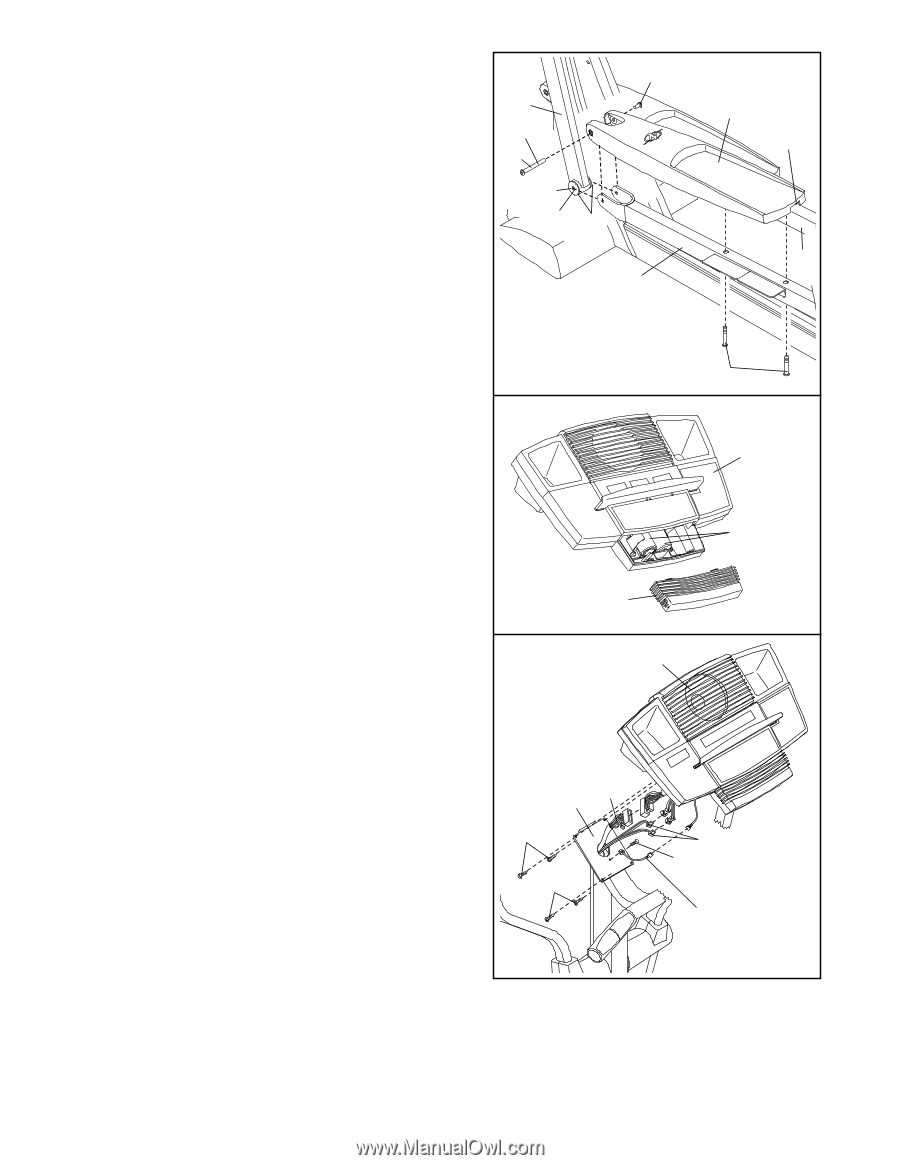
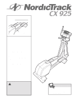
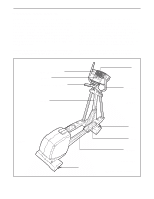
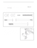
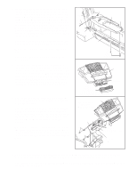
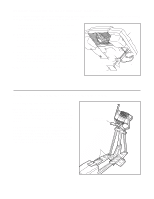
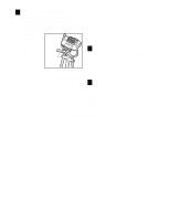
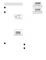
5. Identify the Left Pedal (10), which has a notch near the right side. Place the Left Pedal on the Left Pedal Leg (4). Next, apply the entire contents of one of the included Teflon® lubricant packets to the long side of an M8 x 79mm Bolt Set (65) and the faces of the two indicated Upper Body Arm Bushings (12). Have a second person hold the lower end of the left Upper Body Arm (29) inside of the bracket on the Left Pedal Leg. Align the indicated holes, and attach the Left Pedal and the left Upper Body Arm to the Left Pedal Leg with the M8 x 79mm Bolt Set. Attach the other end of the Left Pedal (10) to the Left Pedal Leg (4) with two M8 x 54mm Button Screws (83). Repeat this step on the right side of the elliptical exerciser. See step 2. Tighten the two M10 x 108mm Button Screws (70). 6. The Console (17) requires four "D" batteries (not included); alkaline batteries are recommended. Slide the battery cover off the Console. Insert four batteries into the battery compartment. Make sure that the batteries are oriented as shown by the diagram inside the battery compartment. Slide the battery cover back onto the Console. Note: When the batteries are installed correctly, the fan will turn on for a moment. 7. Remove the ground wire screw from the Upright (2). Attach the ground wire to the Upright with the ground wire screw as shown. Have another person hold the Console (17) near the Upright (2). Connect the ground wire to the ground wire on the Console. Connect the Upper Wire Harness (30) to the wire harness on the Console. Connect the two Pulse Wires (20) to the pulse wires on the Console. Carefully insert all excess wiring down into the Upright (2). Attach the Console to the Upright with four M4 x 16mm Screws (94). (Note: The Screws may be found in the console box.) Be careful to avoid pinching the wires. 5 65 29 Lube 65 Face Lube 12 4 10 Notch 5 83 6 17 Battery Cover 7 17 Do not pinch the wires during this step. Batteries 30 2 94 94 20 Ground Wire Screw Ground Wire 8. Make sure that all parts of the elliptical exerciser are properly tightened. Cover the floor beneath the elliptical exerciser to protect the floor from damage. Note: Some extra hardware may be left over. The elliptical exerciser is now fully assembled. If you have purchased the optional chest pulse sensor (see page 18), see page 7. 6
-
 1
1 -
 2
2 -
 3
3 -
 4
4 -
 5
5 -
 6
6 -
 7
7 -
 8
8 -
 9
9 -
 10
10 -
 11
11 -
 12
12 -
13
-
14
-
15
-
16
-
17
-
18
-
19
-
20
-
21
-
22
-
23
-
24
 |
 |