NordicTrack Cx 925 Elliptical English Manual - Page 5
two M10 x 108mm Button Screws 70, two M10 Split
 |
View all NordicTrack Cx 925 Elliptical manuals
Add to My Manuals
Save this manual to your list of manuals |
Page 5 highlights
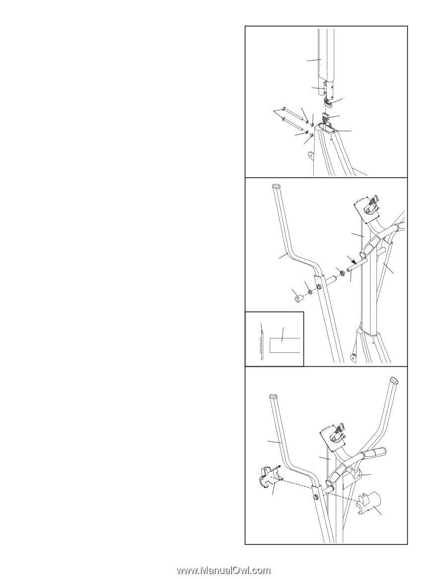
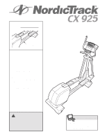
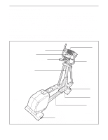
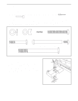
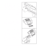
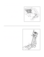
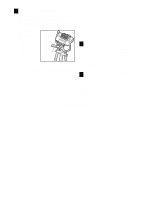
2. Have another person hold the Upright (2) in the position shown. Make sure that the Upright is turned as 2 shown in drawing 3 below, and that the Upper Wire Harness (30) is on the right side of the indicated metal plate. 2 Connect the Upper Wire Harness (30) to the Lower Wire Harness (42). Carefully pull the upper end of the Upper Wire Harness to remove the slack from the Wire Harnesses. Insert the Upright (2) into the Frame (1). Be careful to avoid disconnecting or Plate 30 73 70 47 42 pinching the Wire Harnesses. Attach the Upright with two M10 x 108mm Button Screws (70), two M10 Split Washers (73), and two 7.6mm Spacers (47). Make sure that the curved sides of the Spacers are fac- 1 73 47 ing the Upright. Be careful to avoid damaging the Wire Harnesses with the Button Screws. Do not tighten the Button Screws yet. 3 3. Slide a Weld Spacer (28) onto the axle on the left side of the Upright (2), with the open side of the Weld Spacer facing the Upright. Apply a small amount of grease to the axle. Slide an Upper Body Arm (29) onto the axle on the left side of the Upright (2). Using the included Push Nut Tool (96), tap a Push Nut (31) onto the axle; make sure that the Push Nut is turned as shown in the inset drawing. Attach the other Upper Body Arm (29) to the right side of the Upright (2) in the same way. 2 Grease 29 28 31 29 96 Axle 31 Axle 4. Look inside one of the Handlebar Covers (26) and locate the square tabs connecting the two halves. 4 Gently lift the tabs and disconnect the halves. Hold the two halves of the Handlebar Cover (26) around the tube on the left side of the Upright (2). Align the halves and press them together until they lock. Attach the other Handlebar Cover (26) to the right side 29 of the Upright (2) in the same way. 2 26 5 26 26
-
 1
1 -
 2
2 -
 3
3 -
 4
4 -
 5
5 -
 6
6 -
 7
7 -
 8
8 -
 9
9 -
 10
10 -
 11
11 -
12
-
13
-
14
-
15
-
16
-
17
-
18
-
19
-
20
-
21
-
22
-
23
-
24
 |
 |