NordicTrack Ellipse 910 Elliptical English Manual - Page 7
elliptical
 |
View all NordicTrack Ellipse 910 Elliptical manuals
Add to My Manuals
Save this manual to your list of manuals |
Page 7 highlights
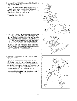
5. Set the Pedal Arm (7) with the Left Pedal (13) on the left side of the elliptical crosstrainer. Hold the indicated end of the Pedal Arm (7) inside the bracket on the left Connecting Arm (8). Insert a Pivot Shaft (6) through both parts. Make sure that the head of the Pivot Shaft is seated in the square hole in the Connecting Arm. Tighten an M10 Nylon Locknut (34) with an M10 Flat Washer (36) onto the Pivot Shaft (6). Press a Nut Cap (33) onto the Nylon Locknut. Attach the other Pedal Arm (7) to the right Connecting Arm (not shown) in the same way. 5 13 7 fD 8 6 36 34 33 SS 6. Hold the front end of the left Pedal Arm (7) inside the bracket on the Left Handlebar Post (5). Insert a Pivot Shaft (6) through both parts. Make sure that the head of the Pivot Shaft is seated in the square hole in the Left Handlebar Post. Tighten an M10 Nylon Locknut (34) with an M10 Flat Washer (36) onto the Pivot Shaft (6). Press a Nut Cap (33) onto the Nylon Locknut. Attach the right Pedal Arm (7) to the Right Handlebar Post (3) in the same way. 6 5 36 34 • 33 7 7 3 6 a 7 00 0 0 7. Identify the Left Handlebar (6), which is labeled with an "L" sticker. Slide the Left Handlebar (6) onto the Left Handlebar Post (5). Make sure that the Left Handlebar is turned as shown. Attach the Left Handlebar with two Handlebar Bolts (73), two M5 Split Washers (74), and two M6 Nylon Locknuts (68). Attach the Right Handlebar (4) to the Right Handlebar Post (3) in the same way. Refer to the inset drawing. Press the Magnet Clip (79) onto the Right Handlebar (4). Make sure that the Magnet Clip is seated in the indicated hole. 7 6 68 74 5 Hole 4 79 73 4 3
-
 1
1 -
 2
2 -
 3
3 -
 4
4 -
 5
5 -
 6
6 -
 7
7 -
 8
8 -
 9
9 -
 10
10 -
 11
11 -
 12
12 -
13
-
14
-
15
-
16
 |
 |
