NordicTrack Ellipse 950 English Manual - Page 6
Computer
 |
View all NordicTrack Ellipse 950 manuals
Add to My Manuals
Save this manual to your list of manuals |
Page 6 highlights
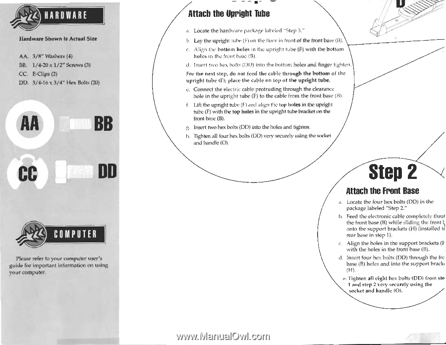
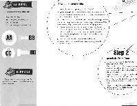
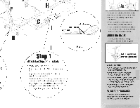
HUME Hardware Shown is Actual Size AA. 3/8" Washers (4) BB. 1/4-20 x 1/2" Screws (3) CC. &Clips (2) DD. 3/4-16 x 3/4" Hex Bolts (20) AA BB CC DD COMPUTER Please refer to your computer user's guide for important information on using, your computer. Attach the Upright Tube a. Locate the hardware package labeled "Step 3." b. Lay the upright tube (F) on the floor in front of the front base (B). c. Align the bottom holes in the upright tube (F) with the bottom holes in the front base (B). d. Insert two hex bolts (DID) into the bottom holes and finger tighten, For the next step, do not feed the cable through the bottom of the upright tube (F); place the cable on top of the upright tube. e. Connect the electric cable protruding through the clearance hole in the upright tube (F) to the cable from the front base (B). f. Lift the upright tube (F) and align the top holes in the upright tube (F) with the top holes in the upright tube bracket on the front base (B). g. Insert two hex bolts (DD) into the holes and tighten. h. "Tighten all four hex bolts (DD) very securely using the socket and handle (O). Step 2 Attach the Front Base a. Locate the four hex bolts (DO) in the package labeled "Step 2." hi. Feed the electronic cable completely throe' the front base (B) while sliding the front onto the support brackets (H) (installed to rear base in step 1). c. Align the holes in the support brackets (Iwith the holes in the front base (B). d. Insert four hex bolts (DO) through the frc base iB) holes and into the support bracki (H). e. Tighten all eight hex bolts (DD) from ste 1 and step 2 very securely using the socket and handle (O).
-
 1
1 -
 2
2 -
 3
3 -
 4
4 -
 5
5 -
 6
6 -
 7
7 -
 8
8
 |
 |