NordicTrack Grt 500 English Manual - Page 7
Slide the Top Weight 16 and the Weight Tube 36
 |
View all NordicTrack Grt 500 manuals
Add to My Manuals
Save this manual to your list of manuals |
Page 7 highlights
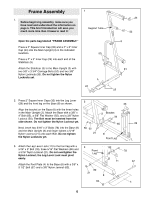
4. Place two Weight Bumpers (19) over the indicated holes in the Stabilizer (5). Insert the two Weight Guides (23) into the Weight Bumpers (19) and the Stabilizer (5). Attach the indicated Weight Guide (23) to the Stabilizer (5) with a 3/8Ó x 2 1/2Ó Bolt (54), two 3/8Ó Flat Washers (55), two 5/8Ó x 1/2Ó Pulley Bushings (42, and a 3/8Ó Nylon Jamnut (63). 5. IMPORTANT: If you purchased the optional weight expansion set, please refer to the userÕs manual accompanying the set to assemble the weights. After you have assembled the weights, refer back to this manual and continue with step 7 on page 8. See the inset drawing. Open the parts bag labeled ÒWeight InsertsÓ. Press two Weight Inserts (77) into the indicated holes in each Weight (26). Make sure the large pin groove is oriented as shown. Slide all of the Weights (26) onto the Weight Guides (23). Make sure the Weights are oriented correctly. The holes must be on the side shown. 4 23 19 63 55 42 19 42 5 50 1 50 Welded 60 Tubes 23 5 55 54 45 3 Slide the Top Weight (16) and the Weight Tube (36) onto the Weight Guides (23). Insert the Weight Tube 16 into the Weights (26). Slide the welded tubes on the Top Frame (1) over the upper ends of the Weight Guides (23). Align the bracket on the Top Frame with the indicated holes in the Main Upright (3). Insert two 3/8Ó x 3Ó Bolts (45) into the holes. Thread a 3/8Ó Nylon Locknut (50) onto the lower Bolt. Do not thread a Locknut onto the upper Bolt yet. 36 26 77 26 Attach the Weight Guides (23) to the Top Frame (1) with two 3/8Ó x 1 3/4Ó Bolts (60) and two 3/8Ó Nylon Locknuts (50). Holes Large Pin Groove 6. Press two 2Ó Square Inner Caps (33) into the Press 6 Frame (12). Disassemble the pre-attached Pivot Rod (27). Attach the Press Frame (12) to the Main Upright (3) with the Pivot Rod, the two Large Washers (53), and the two 3/8Ó Nylon Locknuts (63) as shown. Make sure that the Press Frame is turned so the Large Bushings (87) are at the angle shown. Fully tighten all of the Nylon Locknuts used in steps 1, 2, and 6. 33 63 53 3 63 53 27 12 87 7
-
 1
1 -
 2
2 -
 3
3 -
 4
4 -
 5
5 -
 6
6 -
 7
7 -
 8
8 -
 9
9 -
 10
10 -
 11
11 -
 12
12 -
13
-
14
-
15
-
16
-
17
-
18
-
19
-
20
-
21
-
22
-
23
-
24
-
25
 |
 |
