NordicTrack Pt3 With Freemotion Technology English Manual - Page 7
Attach the Base Plate 3 to the Base Legs 2
 |
View all NordicTrack Pt3 With Freemotion Technology manuals
Add to My Manuals
Save this manual to your list of manuals |
Page 7 highlights
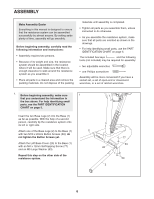
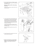
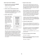
2. Attach the Base Plate (3) to the Base Legs (2) 2 with eight M6 x 20mm Screws (67) and eight M6 Large Washers (61). 2 See step 1. Tighten the M10 x 20mm Button Screws (59). Carefully tip the resistance system back into the operating position. 61 61 67 2 3. Have a second person hold the Backrest (23) near the Base (1). Connect the 4-pin Counter Wire Harness (39) to the 4-pin Console Wire Harness (41). Next, connect the 3-pin Wire Harness (42) to the 3-pin wire harness extending from the Backrest. Carefully push the wire harnesses into the Base. Attach the Backrest (23) to the Base (1) with three M6 x 80mm Button Screws (68) and three M6 Washers (82). Press the Upright Cap (33) into the top of the Base (1). 3 23 3 61 67 67 33 82 68 39 41 42 1 68 82 4. Attach the Seat (24) to the Seat Frame (5) with four M6 x 25mm Screws (72). 4 5. Make sure that all parts are properly tightened. The use of the remaining parts will be explained in ADJUSTMENT, beginning on PAGE 8. 7 24 5 72 72
-
 1
1 -
 2
2 -
 3
3 -
 4
4 -
 5
5 -
 6
6 -
 7
7 -
 8
8 -
 9
9 -
 10
10 -
 11
11 -
 12
12 -
13
-
14
-
15
-
16
-
17
-
18
-
19
-
20
 |
 |
