NordicTrack Viewpoint 8500 Treadmill English Manual - Page 8
If The Connectors Are Not Con
 |
View all NordicTrack Viewpoint 8500 Treadmill manuals
Add to My Manuals
Save this manual to your list of manuals |
Page 8 highlights
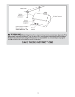
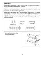
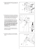
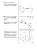
2. Attach the four Base Pads (81) to the base of the Uprights (20) with four 1" Tek Screws (82) in the 2 locations shown. 82 81 81 82 82 81 20 81 82 3. With the help of a second person, carefully raise the Uprights (20) to the vertical position. Remove 3 the band securing the Upright Wire Harness (73) to the right Upright. Have a second person hold the console assembly near the right Upright. Connect the Upright Wire Harness (73) to the console wire extending from the console assembly. See the inset drawing. The connectors should slide together easily and snap into place. If they do not, turn one connector and try again. IF THE CONNECTORS ARE NOT CONNECTED PROPERLY, THE CONSOLE MAY BE DAMAGED WHEN THE POWER IS TURNED ON. Then, insert the connectors into the right Upright (20). Connect the TV Cable (not shown) in the left Upright (not shown) to the cable extending from the console assembly. Console Assembly Console Wire 73 20 73 4. Connect the TV Cable (117) in the left Upright (20) to the cable extending from the console as- 4 sembly. Console Assembly 117 20 8
-
 1
1 -
2
-
 3
3 -
 4
4 -
 5
5 -
 6
6 -
 7
7 -
 8
8 -
 9
9 -
 10
10 -
 11
11 -
 12
12 -
 13
13 -
14
-
15
-
16
-
17
-
18
-
19
-
20
-
21
-
22
-
23
-
24
-
25
-
26
-
27
-
28
-
29
-
30
-
31
-
32
-
33
-
34
-
35
-
36
-
37
-
38
-
39
-
40
 |
 |
