Onkyo TX-NR1000 Owner Manual - Page 15
Front Panel Display - receivers
 |
View all Onkyo TX-NR1000 manuals
Add to My Manuals
Save this manual to your list of manuals |
Page 15 highlights
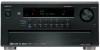
Index Parts and Facilities-Continued B RS 232 This port is for connecting the TX-NR1000/ TX-NR5000E to home automation and external controllers. C PRE OUT A/B To use the TX-NR1000/TX-NR5000E as a preamplifier, connect a power amplifier to this jack. D SPEAKERS A/B These terminals are for connecting the speakers. Two sets of home theater connections are available (simultaneous playback of different sources in each of two home theaters is not supported). Depending on your system, various speaker connections will be available. For example, you can use the surround back speakers for playback in a different room. E AC OUTLET The TX-NR1000/TX-NR5000E is equipped with AC mains outlets for connecting the power cords from other devices so that their power is supplied through the TX-NR1000/TX-NR5000E. By doing this, you can leave the connected device turned on and have the [STANDBY/ON] button on the TX-NR1000/TX-NR5000E turn on and off the Front Panel Display device together with the TX-NR1000/ TX-NR5000E. The shape, number, and total capacity of the AC outlets may differ depending on the area of purchase. Caution: Make sure that the total capacity of the components connected to the TX-NR1000/TX-NR5000E does not exceed the capacity that is printed on the rear panel (e.g., AC 120V - 60Hz SWITCHED 120W 1A MAX.). F AC INLET This connector is for connecting the supplied power cord. G IR IN/OUT These connectors are for connecting the remote sensor of a multiroom kit (sold separately). The connectors are provided for main room, Zone 2, and Zone 3. H 12V TRIGGER OUT These connectors are used to connect to the 12V TRIGGER IN terminal of a component. Available connectors are one with maximum current capacity of 200 mA and four with 100 mA. A Listening mode or input format indicators One of these indicators lights to show the format of the current input source. In addition, one of the listening mode indicators lights to indicate the current listening mode. B Multifunction display During normal operation, shows the current input source. When the FM or AM input is selected, shows the frequency and preset number. When the [DISPLAY] button is pressed, shows the listening mode and input source format. C Audio input signal path indicators Shows from which terminal the audio input signal is coming. D MAIN A/B indicators Indicates which room is currently in use. E SLEEP indicator Lights when the sleep timer is turned on. F Tuning indicators AUTO indicator Lights when receiving FM broadcasts in the stereo mode. Turns off when placed into the monaural mode. RDS indicator (European models only) Lights when an RDS station is being received. TUNED indicator Lights when a radio station is being received. MEMORY indicator Lights when the [MEMORY] button is pressed to preset a radio station. FM STEREO indicator Lights when an FM broadcast station is being received in stereo. Turns off when placed into the monaural mode. G Program format display When the input source is DVD video, Super Audio CD, or compressed digital audio signal such as Dolby Digital and DTS, the channels corresponding to the input source light. H Volume display Shows the volume level. I Video input signal path indicators Shows from which terminal the video input signal is coming. 15
-
 1
1 -
2
-
3
-
4
-
5
-
6
-
7
-
8
-
9
-
 10
10 -
 11
11 -
 12
12 -
 13
13 -
 14
14 -
 15
15 -
 16
16 -
 17
17 -
 18
18 -
 19
19 -
 20
20 -
21
-
22
-
23
-
24
-
25
-
26
-
27
-
28
-
29
-
30
-
31
-
32
-
33
-
34
-
35
-
36
-
37
-
38
-
39
-
40
-
41
-
42
-
43
-
44
-
45
-
46
-
47
-
48
-
49
-
50
-
51
-
52
-
53
-
54
-
55
-
56
-
57
-
58
-
59
-
60
-
61
-
62
-
63
-
64
-
65
-
66
-
67
-
68
-
69
-
70
-
71
-
72
-
73
-
74
-
75
-
76
-
77
-
78
-
79
-
80
-
81
-
82
-
83
-
84
-
85
-
86
-
87
-
88
-
89
-
90
-
91
-
92
-
93
-
94
-
95
-
96
-
97
-
98
-
99
-
100
-
101
-
102
-
103
-
104
-
105
-
106
-
107
-
108
-
109
-
110
-
111
-
112
-
113
-
114
-
115
-
116
-
117
-
118
-
119
-
120
-
121
-
122
-
123
-
124
-
125
-
126
-
127
-
128
-
129
-
130
-
131
-
132
-
133
-
134
-
135
-
136
-
137
-
138
-
139
-
140
-
141
-
142
-
143
-
144
-
145
-
146
-
147
-
148
-
149
-
150
-
151
-
152
 |
 |
