Onkyo TX SR501 Owner Manual - Page 15
Connecting Your AV Components, Connecting a VCR for Recording, Connecting a Camcorder, Games, - tx sr501e manual
 |
UPC - 751398005213
View all Onkyo TX SR501 manuals
Add to My Manuals
Save this manual to your list of manuals |
Page 15 highlights
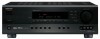
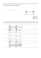
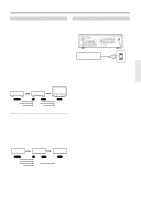
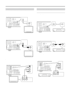
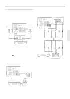
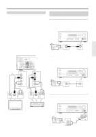
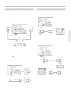
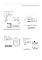
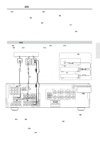
Connecting Your AV Components-Continued Connecting a VCR for Recording If your TV has AV outputs and you want to record from your TV to your VCR via the TX-SR501/TX-SR501E, make the following connections. • Use an S-Video cable to connect the TX-SR501/ TX-SR501E's S VIDEO VIDEO 2 IN to an S-Video output on your TV, and use another S-Video cable to connect the TX-SR501/TX-SR501E's S VIDEO VIDEO 1 OUT to an S-Video input on your VCR, as shown. OR • Use a composite video cable to connect the TX-SR501/ TX-SR501E's VIDEO VIDEO 2 IN to a composite video output on your TV, and use another composite video cable to connect the TX-SR501/TX-SR501E's VIDEO VIDEO 1 OUT to a composite video input on your VCR, as shown. Use an RCA/phono audio cable to connect the TX-SR501/ TX-SR501E's L/R VIDEO 2 IN connectors to the analog audio outputs on your TV, and use another RCA/phono audio cable to connect the TX-SR501/TX-SR501E's L/R VIDEO 1 OUT connectors to the analog audio inputs on your VCR, as shown. Connect one or the other COMPONENT VIDEO ANTENNA VIDEO 1 / 2 / 3 DVD IN IN OUT AM FM 75 Y PB PR DIGITAL INPUT OPTICAL COAXIAL 2 1 REMOTE CONTROL VIDEO 2 IN VIDEO 1 OUT IN DVD MONITOR IN OUT VIDEO S VIDEO IN OUT IN L SUBWOOFER PRE OUT R CD TAPE IN OUT IN FRONT SURR CENTER L L R VIDEO 2 VIDEO 1 R DVD SUB WOOFER VIDEO 2 IN VIDEO S VIDEO IN VIDEO 1 OUT VIDEO S VIDEO OUT Connecting a Camcorder, Games Console, etc. Video Connections ■ Using S-Video Use an S-Video cable to connect the TX-SR501/ TX-SR501E's S VIDEO VIDEO 3 INPUT to the S-Video output on your camcorder, games console, etc., as shown. • Your TV must also be connected via S-Video. STANDBY/ON POWER ON OFF A SPEAKERS B PHONES STANDBY DISPLAY SUBWOOFER DIMMER DIGITAL INPUT MODE CH SEL LEVEL CONTROL SUBWOOFER LEVEL DIRECT STEREO SURROUND DSP ADJUST SPEAKER ADJUST AUDIO ADJUST MASTER VOLUME AUDIO SELECTOR DVD VIDEO 1 VIDEO 2 VIDEO 3 VCR TAPE TUNER C D VIDEO 3 INPUT S VIDEO VIDEO L AUDIO R S VIDEO OUT Camcorder, games console, etc. S VIDEO ■ Using Composite Video Use a composite video cable to connect the TX-SR501/ TX-SR501E's VIDEO VIDEO 3 INPUT to the composite video output on your camcorder, games console, etc., as shown. • Your TV must also be connected via composite video. STANDBY/ON POWER ON OFF A SPEAKERS B PHONES STANDBY DISPLAY SUBWOOFER DIMMER DIGITAL INPUT MODE CH SEL LEVEL CONTROL SUBWOOFER LEVEL DIRECT STEREO SURROUND DSP ADJUST SPEAKER ADJUST AUDIO ADJUST MASTER VOLUME AUDIO SELECTOR DVD VIDEO 1 VIDEO 2 VIDEO 3 VCR TAPE TUNER C D VIDEO 3 INPUT S VIDEO VIDEO L AUDIO R VIDEO 2 Connect one or the other VIDEO 1 VIDEO OUT S VIDEO OUT LR AUDIO OUTPUT VIDEO IN S VIDEO IN LR AUDIO INPUT TV VCR Note: The TX-SR501/TX-SR501E must be turned on (not Standby) in order to record. If you want to record from your TV to your VCR without going through the TX-SR501/TX-SR501E, connect your TV's AV outputs directly to your VCR's AV inputs. See the manuals supplied with your TV and VCR for details. VIDEO OUT Camcorder, games console, etc. VIDEO Audio Connections Use an RCA/phono audio cable to connect the TX-SR501/ TX-SR501E's L/R VIDEO 3 INPUT connectors to the analog audio outputs on your camcorder, games console, etc., as shown. STANDBY/ON POWER ON OFF A SPEAKERS B PHONES STANDBY DISPLAY SUBWOOFER DIMMER DIGITAL INPUT MODE CH SEL LEVEL CONTROL SUBWOOFER LEVEL DIRECT STEREO SURROUND DSP ADJUST SPEAKER ADJUST AUDIO ADJUST MASTER VOLUME AUDIO SELECTOR DVD VIDEO 1 VIDEO 2 VIDEO 3 VCR TAPE TUNER C D VIDEO 3 INPUT S VIDEO VIDEO L AUDIO R Camcorder, games console, etc. AUDIO OUTPUT L R L AUDIO R 15
-
 1
1 -
2
-
3
-
4
-
5
-
6
-
7
-
8
-
9
-
 10
10 -
 11
11 -
 12
12 -
 13
13 -
 14
14 -
 15
15 -
 16
16 -
 17
17 -
 18
18 -
 19
19 -
 20
20 -
21
-
22
-
23
-
24
-
25
-
26
-
27
-
28
-
29
-
30
-
31
-
32
-
33
-
34
-
35
-
36
-
37
-
38
-
39
-
40
-
41
-
42
-
43
-
44
-
45
-
46
-
47
-
48
 |
 |