Onkyo TX SR501 Owner Manual - Page 6
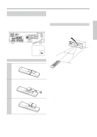
Controls & Connectors - remote
 |
UPC - 751398005213
View all Onkyo TX SR501 manuals
Add to My Manuals
Save this manual to your list of manuals |
Page 6 highlights
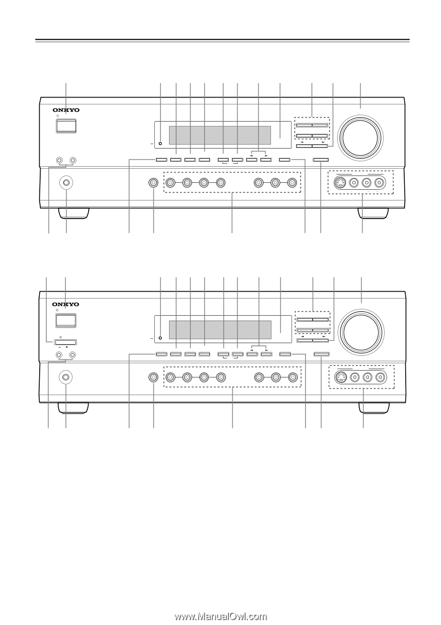
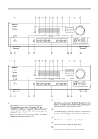
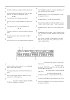
Controls & Connectors Front Panel North American Model 2 3 456 78 9 J KL M STANDBY/ON A SPEAKERS B PHONES STANDBY DISPLAY SUBWOOFER DIMMER DIGITAL INPUT MODE MEMORY FM MODE CLEAR AUDIO SELECTOR DVD VIDEO 1 VIDEO 2 VIDEO 3 VCR DIRECT STEREO SURROUND DSP PRESET/ADJUST TUNING SPEAKER ADJUST AUDIO ADJUST MASTER VOLUME TAPE TUNER C D VIDEO 3 INPUT S VIDEO VIDEO L AUDIO R NO Other Models 12 STANDBY/ON POWER ON OFF A SPEAKERS B PHONES PQ R ST U 3 456 78 9 J KL M STANDBY DISPLAY SUBWOOFER DIMMER DIGITAL INPUT MODE MEMORY FM MODE CLEAR AUDIO SELECTOR DVD VIDEO 1 VIDEO 2 VIDEO 3 VCR DIRECT STEREO SURROUND DSP PRESET/ADJUST TUNING SPEAKER ADJUST AUDIO ADJUST MASTER VOLUME TAPE TUNER C D VIDEO 3 INPUT S VIDEO VIDEO L AUDIO R NO PQ For detailed information, refer to the pages in parenthesis. A POWER switch (24) The North American model doesn't have this switch. This is the main power switch. When set to OFF, the TX-SR501/TX-SR501E is completely shutdown. When set to ON, the TX-SR501/TX-SR501E is in Standby mode and the STANDBY indicator lights up. Don't turn on the power until you've completed, and double checked all connections (pages 10-23). Note: Turning on the TX-SR501/TX-SR501E may cause a momentary power surge that might interfere with other electrical equipment on the same circuit. If this is a problem, plug the TX-SR501/TX-SR501E into a different branch circuit. R ST U B STANDBY/ON button (24) This button is used to set the TX-SR501/TX-SR501E to On or Standby. For models with a POWER switch, this button has no effect unless the POWER switch is set to ON. C STANDBY indicator (24) This indicator lights up when the TX-SR501/TX-SR501E is in Standby mode, and it flashes while a signal is being received from the remote controller. D DIMMER button (32) This button is used to adjust the display brightness. E DIGITAL INPUT button (24) This button is used to assign the digital inputs. F SUBWOOFER MODE button (25) This button is used to select the Subwoofer modes. 6
-
 1
1 -
 2
2 -
 3
3 -
 4
4 -
 5
5 -
 6
6 -
 7
7 -
 8
8 -
 9
9 -
 10
10 -
 11
11 -
 12
12 -
13
-
14
-
15
-
16
-
17
-
18
-
19
-
20
-
21
-
22
-
23
-
24
-
25
-
26
-
27
-
28
-
29
-
30
-
31
-
32
-
33
-
34
-
35
-
36
-
37
-
38
-
39
-
40
-
41
-
42
-
43
-
44
-
45
-
46
-
47
-
48
 |
 |