Onkyo TX SR501 Owner Manual - Page 21
Installing Your Speakers, Connecting Your Speakers - no sound
 |
UPC - 751398005213
View all Onkyo TX SR501 manuals
Add to My Manuals
Save this manual to your list of manuals |
Page 21 highlights
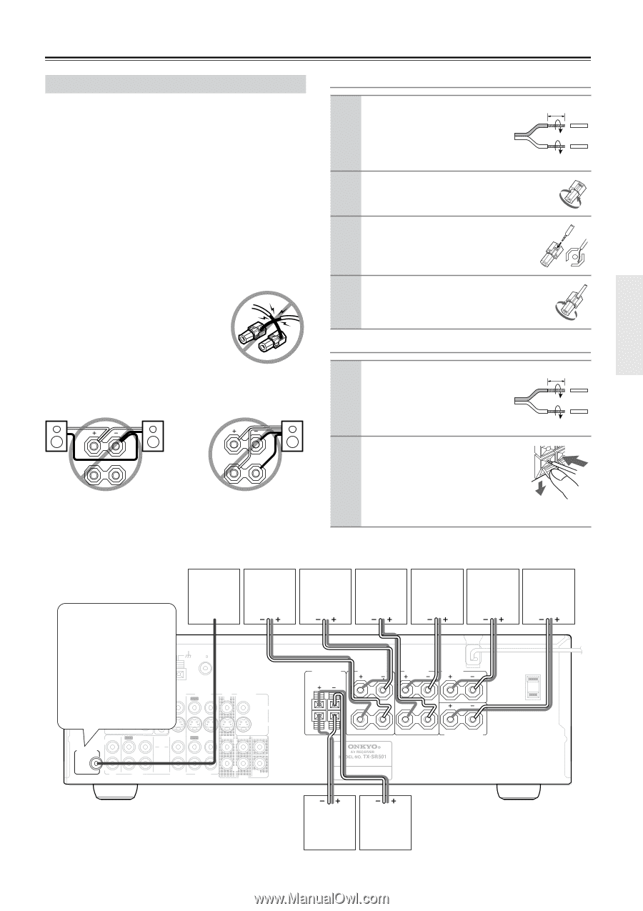
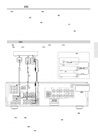
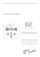
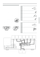
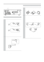
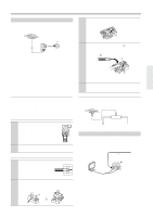
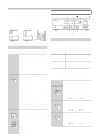
Installing Your Speakers-Continued Connecting Your Speakers Before you connect your speakers, read the following: • Disconnect the power cord from the wall outlet. • Read the instructions supplied with your speakers. • Pay close attention to speaker wiring polarity. In other words, connect positive (+) terminals only to positive (+) terminals, and negative (-) terminals only to negative (-) terminals. If you get them the wrong way around, the sound will be out of phase and will sound odd. • Only use speakers with an impedance of between 6 and 16 ohms. Connecting speakers with an impedance of less than 6 ohms may damage your TX-SR501/TX-SR501E. • Unnecessarily long, or very thin speaker cables may affect the sound quality and should be avoided. • Be careful not to short the positive and negative connections. Doing so may damage your TX-SR501/TX-SR501E. • Don't connect more than one cable to each speaker terminal. Doing so may damage your TX-SR501/TX-SR501E. • If you want to connect a single speaker instead of a pair of speakers, don't connect it to both the left and right speaker terminals. L L R R Connecting Speaker Set A 1 Strip 5/8" (15 mm) of insulation from the ends of the speaker cables, and twist the bare wires tightly, as shown. 2 Unscrew the terminal. 3 Fully insert the wire. 5/8" (15 mm) 4 Screw the terminal tight. Connecting Speaker Set B 1 Strip 3/8" (10 mm) of insulation from the ends of the speaker cables, and twist the bare wires tightly, as shown. 3/8" (10 mm) 2 While pressing the lever, insert the wire into the hole, and then release the lever. Make sure that the terminals are gripping the bare wires, not the insulation. The following illustration shows which speakers should be connected to which terminals. Speakers Set A Active subwoofer Frontright speaker The SUBWOOFER PRE OUT should be connected to the input on your active subwoofCeOMrP.OINfENyT oVIDuEOr ANTENNA VIDEO 1 / 2 / 3 subwoINofer DVD IN OUT doesn't hYave an AM FM 75 amp built-in, you'll need to use an external ampPB. See the manual suppliedPRwith VIDEO 2 IN your subwoofer for more DIGITAL INPUT REMOTE CONTROL OPTICAL COAXIAL information. 2 1 VIDEO 1 OUT IN DVD MONITOR IN OUT VIDEO S VIDEO IN OUT IN L SUBWOOFER PRE OUT R CD TAPE IN OUT IN FRONT SURR CENTER L L R VIDEO 2 VIDEO 1 R DVD SUB WOOFER Frontleft speaker Surroundright speaker Surroundleft speaker Center speaker Surroundback speaker FRONT SPEAKERS B FRONT SPEAKERS A L SURROUND SPEAKERS L CENTER SPEAKER AC OUTLET AC 120V 60 Hz SWITCHED 120W 1 A MAX. L R R R SURROUND BACK SPEAKER Frontright speaker Frontleft speaker Speakers Set B 21
-
 1
1 -
2
-
3
-
4
-
5
-
6
-
7
-
8
-
9
-
10
-
11
-
12
-
13
-
14
-
15
-
 16
16 -
 17
17 -
 18
18 -
 19
19 -
 20
20 -
 21
21 -
 22
22 -
 23
23 -
 24
24 -
 25
25 -
 26
26 -
27
-
28
-
29
-
30
-
31
-
32
-
33
-
34
-
35
-
36
-
37
-
38
-
39
-
40
-
41
-
42
-
43
-
44
-
45
-
46
-
47
-
48
 |
 |