Onkyo TX-SR701 Owner Manual - Page 27
Connecting speakers, Connecting the speaker cable - av
 |
UPC - 751398005183
View all Onkyo TX-SR701 manuals
Add to My Manuals
Save this manual to your list of manuals |
Page 27 highlights
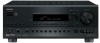
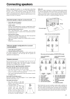
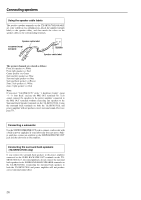
Connecting speakers Front right speaker Center speaker Front left speaker ANTENNA AM COMPONENT VIDEO INPUT 2 INPUT 1 OUTPUT Y PB FM 75 ZONE 2 LINE OUT L ZONE 2 SPEAKERS L PR DIGITAL IN OUT OPTICAL 2 1 OPTICAL VIDEO 3 COAXIAL IN VIDEO 2 OUT IN IN GND L IN COAXIAL IN OUT IN IN OUT IN R VIDEO 1 OUT IN DVD IN R REMOTE CONTROL MONITOR OUT V ZONE 2 12 V TRIGGER OUT S IR IN OUT IN FRONT SURR CENTER L R PHONO CD TAPE VIDEO 3 VIDEO 2 VIDEO 1 R DVD SUB WOOFER CAUTION: SPEAKER IMPEDANCE 6 OHMS MIN. /SPEAKER FRONT SPEAKERS SURROUND SPEAKERS L CENTER SPEAKER AC OUTLETS R ZONE 2 FRONT L PRE OUT R SURR SURROUND CENTER SURR BACK BACK (SB) SPEAKER L AC 230-240V 50 Hz SWITCHED TOTAL 100W MAX. SUB WOOFER R AV RECEIVER MODEL NO. TX-SR 701E Surround right speaker Subwoofer Surround back speaker Surround left speaker Connecting speakers After determining the layout of your speaker system, it is now necessary to connect the speakers correctly to your TX-SR701/ 701E/601/601E. Caution: • Be sure to connect the positive (+) and negative (-) cables for the speakers properly. If they are mixed up, the left and right signals will be reversed and the audio will sound unnatural. • Do not connect more than one speaker cable to one speaker terminal. Doing so may damage the TX-SR701/701E/601/ 601E. • Connect only speakers with an impedance between 6 and 16 Ω to the TX-SR701/701E/601/601E. Connecting speakers with an impedance lower than 6 Ω may damage the amplifier. • Even if you are using only one speaker or listening to monaural (mono) sound, never connect a single speaker in parallel to both the right and left-channel terminals. • To prevent damage to circuitry, never short-circuit the positive (+) and negative (-) speaker wires. NO! Connecting the speaker cable 1. Strip away approx. 5/8 inch (15 mm) of the wire insulation. 2. Twist the wire ends tightly together. 3. Unscrew the speaker terminal cap. 5/8" (15mm) SPEAKERS -+ L L R - R + SPEAKERS -+ L L R - R + 4. Insert the exposed wire end. 5. Screw down the speaker terminal cap. 27
-
 1
1 -
2
-
3
-
4
-
5
-
6
-
7
-
8
-
9
-
10
-
11
-
12
-
13
-
14
-
15
-
16
-
17
-
18
-
19
-
20
-
21
-
 22
22 -
 23
23 -
 24
24 -
 25
25 -
 26
26 -
 27
27 -
 28
28 -
 29
29 -
 30
30 -
 31
31 -
 32
32 -
33
-
34
-
35
-
36
-
37
-
38
-
39
-
40
-
41
-
42
-
43
-
44
-
45
-
46
-
47
-
48
-
49
-
50
-
51
-
52
-
53
-
54
-
55
-
56
-
57
-
58
-
59
-
60
-
61
-
62
-
63
-
64
-
65
-
66
-
67
-
68
-
69
-
70
-
71
-
72
-
73
-
74
-
75
-
76
-
77
-
78
-
79
-
80
 |
 |
