Panasonic CF-53AAGZX1M User Manual - Page 12
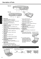
Attaching the stylus to the computer
 |
View all Panasonic CF-53AAGZX1M manuals
Add to My Manuals
Save this manual to your list of manuals |
Page 12 highlights
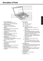
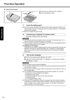
Troubleshooting Useful Information Getting Started Description of Parts Right side Rear side AB C D E F GH Bottom Q R S T I F J K L MNO P A : Battery pack Specified Battery pack: CF-VZSU71U B : ExpressCard slot*2 / PC Card slot*3 Î Reference Manual "PC Card / ExpressCard" *2 Only for model with ExpressCard slot *3 Only for model without ExpressCard slot C : PC Card slot Î Reference Manual "PC Card / ExpressCard" D : SD Memory Card slot Î Reference Manual "SD Memory Card" E : Wireless switch Î Reference Manual "Disabling/Enabling Wireless Communication" "Wireless LAN" "Bluetooth" "Wireless WAN" F : USB 2.0 port Î Reference Manual "USB Devices" G : USB 3.0 port Î Reference Manual "USB Devices" H : DC-IN jack I : LAN port Î Reference Manual "LAN" J : HDMI Port Î Reference Manual "External Display" K : VGA port Î Reference Manual "External Display" L : Ventilation hole (Exhaust) M : Security lock A Kensington cable can be connected. For further information, read the manual that comes with the cable. N : SIM Card slot Î Reference Manual "Wireless WAN" O : 2nd LAN Port*4 / Modem Port*5 / IEEE 1394 Interface Connector*6 *4 Only for model with 2nd LAN Î Reference Manual "LAN" *5 Only for model with Modem Î Reference Manual "Modem" *6 Only for model with IEEE 1394 Î Reference Manual "IEEE 1394 Devices" P : Serial port Q : Expansion bus connector Î Reference Manual "Port Replicator" R : RAM module slot Î Reference Manual "RAM Module" S : Battery latch T : Hard disk drive Î Reference Manual "Hard Disk Drive" NOTE z When you open the covers on (Example: rear side) the right side or the rear side, push down and pull the covers. z This computer contains a magnet and magnetic products at the locations circled in the illustration at right. Avoid leaving metallic object or magnetic media in contact with these areas. Attaching the stylus to the computer A Use the tether to attach the stylus to the computer so you will not lose it. There are holes (A) to attach it. 1 2 3 4 Appendix 12
-
 1
1 -
2
-
3
-
4
-
5
-
6
-
 7
7 -
 8
8 -
 9
9 -
 10
10 -
 11
11 -
 12
12 -
 13
13 -
 14
14 -
 15
15 -
 16
16 -
 17
17 -
18
-
19
-
20
-
21
-
22
-
23
-
24
-
25
-
26
-
27
-
28
-
29
-
30
-
31
-
32
-
33
-
34
-
35
-
36
-
37
-
38
-
39
-
40
 |
 |
