Panasonic CF-73SCUTSBM Service Manual - Page 18
Diagnosis
 |
UPC - 092281843346
View all Panasonic CF-73SCUTSBM manuals
Add to My Manuals
Save this manual to your list of manuals |
Page 18 highlights
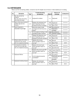
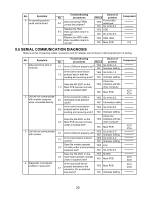
9 Diagnosis 9.1 MAIN UNIT DIAGNOSIS(1/2) Make sure that connecting cables, connectors and AC adapter are not loose or disconnected prior to testing. No. Symptom 1 No power is sent to the unit. (When using AC) No power is sent to the unit. (When using the Battery Pack) 2 Power cuts off during operation. Troubleshooting Source of No. procedures Result problem 1-1 Is 15V applied to pins 1-3 of Q710? (Whichever one)? YES Go to No.1-3 NO Go to No.1-2 1-2 Is 15V applied to pins 5-8 of Q699? YES Go to No.1-3 NO Go to No.1-2 Component Q699 Before setting the power 1-3 switch to ON, check voltage on either side of SW1000 Is Voltage 3.3V? YES NO If voltage is 0V during the power switch is set to ON. If not 0V If voltage of C738 is 3.3V SW1000 R705 R706 If lower than 3V IC617 1-5 Is 8-12V applied to pins 1 of Q681? (Whichever one) Check soldered parts of 2-1 D666 ~ D668 D463 ~ D468. YES If voltage is 8-12V NO Main PCB If they show NO soldered completely YES Q681 R589 R584, R585 R501 ~R506 IC605, IC606 IC616 9.2 MAIN UNIT DIAGNOSIS(2/2) Make sure that connecting cables, connectors and AC adapter are not loose or disconnected prior to testing. No. Symptom 1 When a device is selected for "Boot Up Drive", the system boots from a different device. 2 Date or Time cannot be input. Date and Time does not change properly. Date and Time are not displayed. Troubleshooting No. procedures 1-1 Are there system files in the device selected? Does the unit operate 1-2 normally after replacing the problem device. Result Source of problem YES Go to No.1-2 NO Improper setting Device for which YES the problem occurred NO Main PCB Component IC3 2-1 Replace the Main PCB. Main PCB IC3 X2 RTC battery 3 Memory count is too large or too small. 3-1 Replace the Main PCB. Main PCB IC4-11 IC2 15
-
 1
1 -
2
-
3
-
4
-
5
-
6
-
7
-
8
-
9
-
10
-
11
-
12
-
 13
13 -
 14
14 -
 15
15 -
 16
16 -
 17
17 -
 18
18 -
 19
19 -
 20
20 -
 21
21 -
 22
22 -
 23
23 -
24
-
25
-
26
-
27
-
28
-
29
-
30
-
31
-
32
-
33
-
34
-
35
-
36
-
37
-
38
-
39
-
40
-
41
-
42
-
43
-
44
-
45
-
46
-
47
-
48
-
49
-
50
-
51
-
52
-
53
-
54
-
55
-
56
-
57
-
58
-
59
-
60
-
61
-
62
-
63
-
64
-
65
-
66
-
67
-
68
-
69
-
70
-
71
-
72
-
73
-
74
-
75
-
76
-
77
-
78
-
79
-
80
-
81
-
82
-
83
-
84
-
85
-
86
-
87
-
88
-
89
-
90
-
91
-
92
-
93
-
94
-
95
-
96
-
97
-
98
-
99
-
100
-
101
-
102
-
103
-
104
-
105
-
106
-
107
-
108
-
109
-
110
-
111
-
112
-
113
-
114
-
115
-
116
-
117
-
118
 |
 |
