Panasonic CF-73SCUTSBM Service Manual - Page 25
Diagnostic Test
 |
UPC - 092281843346
View all Panasonic CF-73SCUTSBM manuals
Add to My Manuals
Save this manual to your list of manuals |
Page 25 highlights
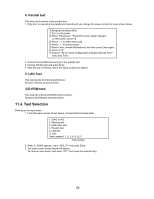
10 Diagnostic Test Diagnostic Test Procedure 10.1. Equipment (1) Test Computer 1 unit (2) IO BOX (CF-VEBU03 1 unit (3) External Floppy Disk Drive (USB Port 1 unit (4) AC Adapter 1 pc. (5) External Printer 1 unit (6) Loopback Plug (Parallel Port Test) [P/N: DFWV95C0081 1 pc. (7) Loopback Plug (Serial Port Test for RS232C) [P/N: DFWV95C0067] ----- 1 pc. (8) Floppy Disk containing file DIAG 1 pc. 10.2. Preparation (1) Connect the computer to the IO BOX (CF-VEBU03). (2) Connect the AC Adapter and External Equipments. (3) The System Setup should be set to the factory setting values by executing the "SETUP UTILITY" which can be invoked by F2 key at the POST. If not, the messages and items of the diagnostic test may not be displayed properly on the LCD. (4) The serial port must be enabled in the "SETUP UTILITY" in order to execute the "1st SERIAL PORT" test. (5) Connect the serial loopback plug. (6) In order to test the parallel port with Loopback Plug, disconnect the printer cable and connect the parallel loopback plug with Power OFF. 10.3. NOTICE When "Enter password" is displayed, use "Password Skipping Plug" in order to skip the user password. 1) Connect the parallel plug to the parallel port. 2) Connect the PS/2 mouse plug to the mouse port. 3) Power on the computer. The wiring of the parallel plug is described below. Connect pins 2-5-6-8-11-13-15-18-19-20-21-22-23 to Shield GND (PS/2 mouse plug pin 3.) Connect pins 3-4-7-9-10-12 to VC5 (PS/2 mouse plug pin 4) with 4.7KW each. CAUTION The plug described above must be used for servicing purpose only. Do not use it for other than the above purpose and ensure that it remains confidential. Using the plug enables the user to skip the previous password and disable the password. 22
-
 1
1 -
2
-
3
-
4
-
5
-
6
-
7
-
8
-
9
-
10
-
11
-
12
-
13
-
14
-
15
-
16
-
17
-
18
-
19
-
 20
20 -
 21
21 -
 22
22 -
 23
23 -
 24
24 -
 25
25 -
 26
26 -
 27
27 -
 28
28 -
 29
29 -
 30
30 -
31
-
32
-
33
-
34
-
35
-
36
-
37
-
38
-
39
-
40
-
41
-
42
-
43
-
44
-
45
-
46
-
47
-
48
-
49
-
50
-
51
-
52
-
53
-
54
-
55
-
56
-
57
-
58
-
59
-
60
-
61
-
62
-
63
-
64
-
65
-
66
-
67
-
68
-
69
-
70
-
71
-
72
-
73
-
74
-
75
-
76
-
77
-
78
-
79
-
80
-
81
-
82
-
83
-
84
-
85
-
86
-
87
-
88
-
89
-
90
-
91
-
92
-
93
-
94
-
95
-
96
-
97
-
98
-
99
-
100
-
101
-
102
-
103
-
104
-
105
-
106
-
107
-
108
-
109
-
110
-
111
-
112
-
113
-
114
-
115
-
116
-
117
-
118
 |
 |
