Panasonic CQC1300U CQC1300U User Guide - Page 16
Installation Guide - cq c1300u wiring
 |
View all Panasonic CQC1300U manuals
Add to My Manuals
Save this manual to your list of manuals |
Page 16 highlights
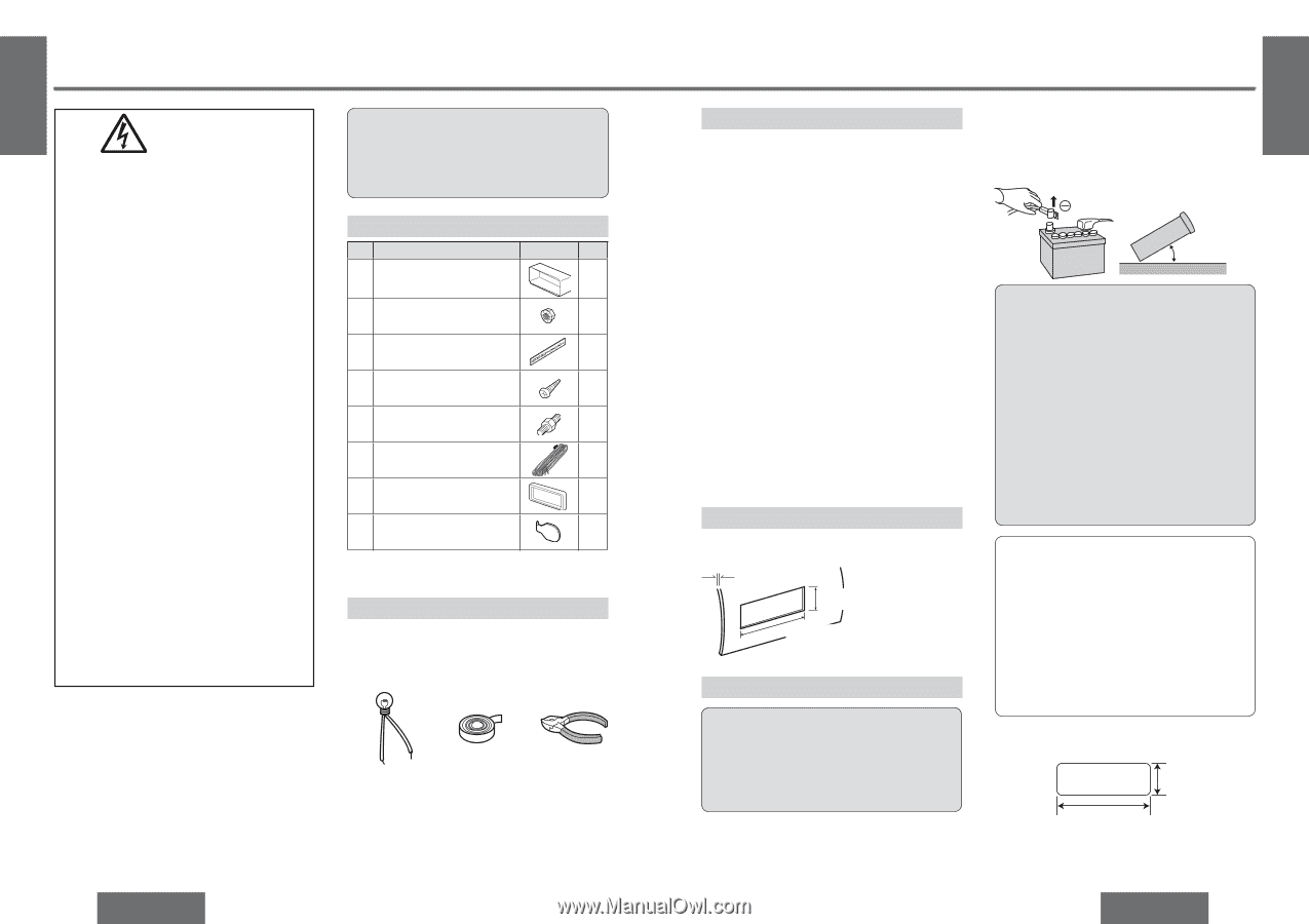
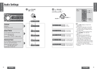
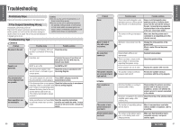
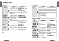
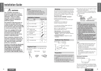
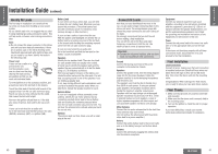
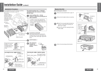
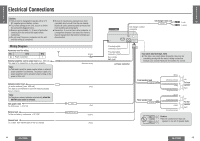
E N G Installation Guide L I S H 25 WARNING This installation information is designed for experienced installers and is not intended for non-technical individuals. It does not contain warnings or cautions of potential dangers involved in attempting to install this product. Any attempt to install this product in a motor car by anyone other than a qualified installer could cause damage to the electrical system and could result in serious personal injury or death. If your car is equipped with air bag and/or anti-theft systems specific procedures may be required for connection and disconnection of the battery to install this product. Before attempting installation of this electronic component contact your car dealer or manufacturer to determine the required procedure and strictly follow their instructions. FAILURE TO FOLLOW THE PROCEDURE MAY RESULT IN THE UNINTENDED DEPLOYMENT OF AIR BAGS OR ACTIVATION OF THE ANTI-THEFT SYSTEM RESULTING IN DAMAGE TO THE VEHICLE AND PERSONAL INJURY. Caution: ≥ This unit operates with a 12 V DC negative ground auto battery system only. Do not attempt to use it in any other system. Doing so could cause serious damage. Installation Hardware No. Item Diagram Q'ty 1 Mounting collar 1 2 Hex. nut (5 mm‡) 1 3 Rear support strap 1 4 Tapping screw 1 (5 mm‡k16 mm) 5 Mounting bolt 1 (5 mm‡) 6 Power connector 1 7 Trim plate 1 8 Lock cancel plate 2 Required Tools You'll need a screwdriver, a 1.5 V AA battery, and the following: 12 V DC Test bulb Electrical tape Side-cut pliers 38 CQ-C1300U Overview This product should be installed by a professional. However, if you plan to install this product yourself, your first step is to decide where to install it. The instructions in these pages will guide you through the remaining steps: (Please refer to the "WARNING" statement.) ≥ Identify and label the car wires. ≥ Connect the car wires to the wires of the power connector. ≥ Install the unit in the dashboard. ≥ Check the operation of the unit. If you encounter problems, please consult your nearest professional installer. Before you begin installation, look for the items which are packed with your unit. ≥ Warranty Card... Fill this out promptly. ≥ Panasonic Servicenter List for Service Directory... Keep for future reference in case the product needs servicing. ≥ Installation Hardware... Needed for in-dash installation. Dashboard Specifications Thickness Min. 3/16q (4.75 mm) Max. 7/32q (5.56 mm) 23/32q (53 mm) 75/32q (182 mm) Preparation ≥ We strongly recommend that you wear gloves for installation work to protect yourself from injuries. ≥ When bending the mounting tabs of the mounting collar with a screwdriver, be careful not to injure your hands and fingers. E N G L I ≥ Disconnect the cable from the negative - battery S H terminal (see caution below). ≥ Unit should be installed in a horizontal position 26 with the front end up at a convenient angle, but not more than 30o. Less than 30o Caution: ≥ If your car is equipped with air bag and/or anti-theft systems specific procedures may be required for connection and disconnection of the battery to install this product. ≥ Before attempting installation of this electronic component contact your car dealer or manufacturer to determine the required procedure and strictly follow their instructions. ≥ FAILURE TO FOLLOW THE PROCEDURE MAY RESULT IN THE UNINTENDED DEPLOYMENT OF AIR BAGS OR ACTIVATION OF THE ANTI-THEFT SYSTEM RESULTING IN DAMAGE TO THE VEHICLE AND PERSONAL INJURY. Note: ≥ Various settings that have been stored in the memory in order on-board equipment (car navigation etc.) may be lost if the battery terminals are disconnected. Therefore, we recommend to make a record of or to back up the settings before disconnecting the terminals. After completing installation of the main unit, set the equipment again according to the record. Dashboard Installation Installation Opening 23/32q (53 mm) 75/32q (182 mm) This unit can be installed in any dashboard having an opening as shown above. The dashboard should be 3/16q (4.75 mm)-7/32q (5.56 mm) thick in order to be able to support the unit. CQ-C1300U 39
-
 1
1 -
2
-
3
-
4
-
5
-
6
-
7
-
8
-
9
-
10
-
 11
11 -
 12
12 -
 13
13 -
 14
14 -
 15
15 -
 16
16 -
 17
17 -
 18
18 -
 19
19 -
 20
20 -
 21
21
 |
 |