Panasonic CQC1300U CQC1300U User Guide - Page 19
Electrical Connections
 |
View all Panasonic CQC1300U manuals
Add to My Manuals
Save this manual to your list of manuals |
Page 19 highlights
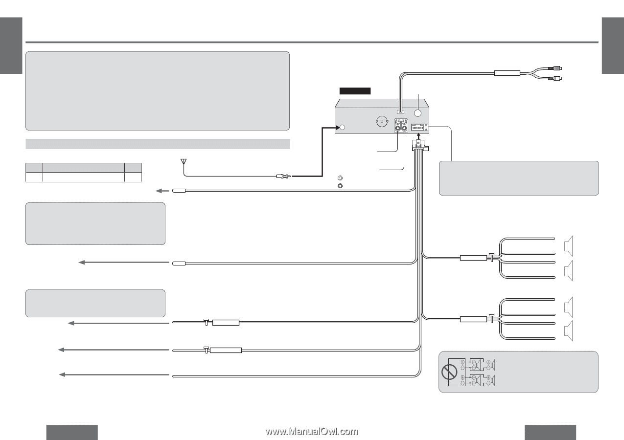
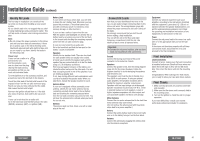
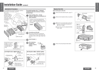
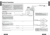
E N G Electrical Connections L I S H Caution: 31 ≥ This product is designed to operate with a 12 V DC, negative ground battery system. ≥ Be sure to insulate any exposed wires from a possible short-circuit from the car chassis. ≥ To prevent damage to the unit, be sure to follow Bundle all cables and keep cable terminals free the connection diagram below. from touching any metal parts. ≥ Remove approximately 1/4q (5 mm) of protective ≥ Remember, if your car has a drive computer or covering from the ends of the leads before a navigation computer, the data of its memory connecting. may be erased when the battery terminals are ≥ Do not insert the power connector into the unit disconnected. until the wiring is completed. Wiring Diagram Accessory used for wiring No. Item Q'ty 6 Power connector 1 External amplifier control power lead (max. 500 mA) This lead is for connection to the power amplifier. Note: ≥ This lead is used for power control when an external power amplifier is connected. The power supply of a power amplifier will be activated when turning on the power of this unit. Antenna (Blue/white stripe) Antenna control lead (to motor antenna) (max. 500 mA) This lead is not intended for use with switch actuated power antenna. Note: ≥ The power antenna extends automatically when the AM/FM radio mode is selected. ACC power lead To ACC power, i12 V DC. Battery lead To the car battery, continuous i12 V DC. Ground lead To a clean, bare metallic part of the car chassis. (Blue) ACC BATTERY 15 A (Red) (Yellow) (Black) 44 CQ-C1300U CQ-C1300U CD changer control connector CD changer input cord CD.C-IN E N G L I S H R (red) 32 L (white) Pre-amp output connector (rear) Pre-amp output connector (front) L (white) R (red) 6 Power connector Fuse (mini auto fuse type, 15 A) ≥ If the fuse (rear panel) blows frequently, they may be something wrong with the unit or wiring connection. Consult your nearest Panasonic Servicenter for service. Front speaker lead FRONT SP Rear speaker lead REAR SP L R (White) + (White/black stripe) + (Gray) - (Gray/black stripe) (Green) + (Green/black stripe) + (Violet) - (Violet/black stripe) Left To front speaker Right Left To rear speaker Right Caution: ≥ Do not connect more than one speaker to one set of speaker leads. CQ-C1300U 45
-
 1
1 -
2
-
3
-
4
-
5
-
6
-
7
-
8
-
9
-
10
-
11
-
12
-
13
-
 14
14 -
 15
15 -
 16
16 -
 17
17 -
 18
18 -
 19
19 -
 20
20 -
 21
21
 |
 |