Panasonic CQC1300U CQC1300U User Guide - Page 18
continued, Remove the Unit, Installation Procedures, b Using the rubber cushion option
 |
View all Panasonic CQC1300U manuals
Add to My Manuals
Save this manual to your list of manuals |
Page 18 highlights
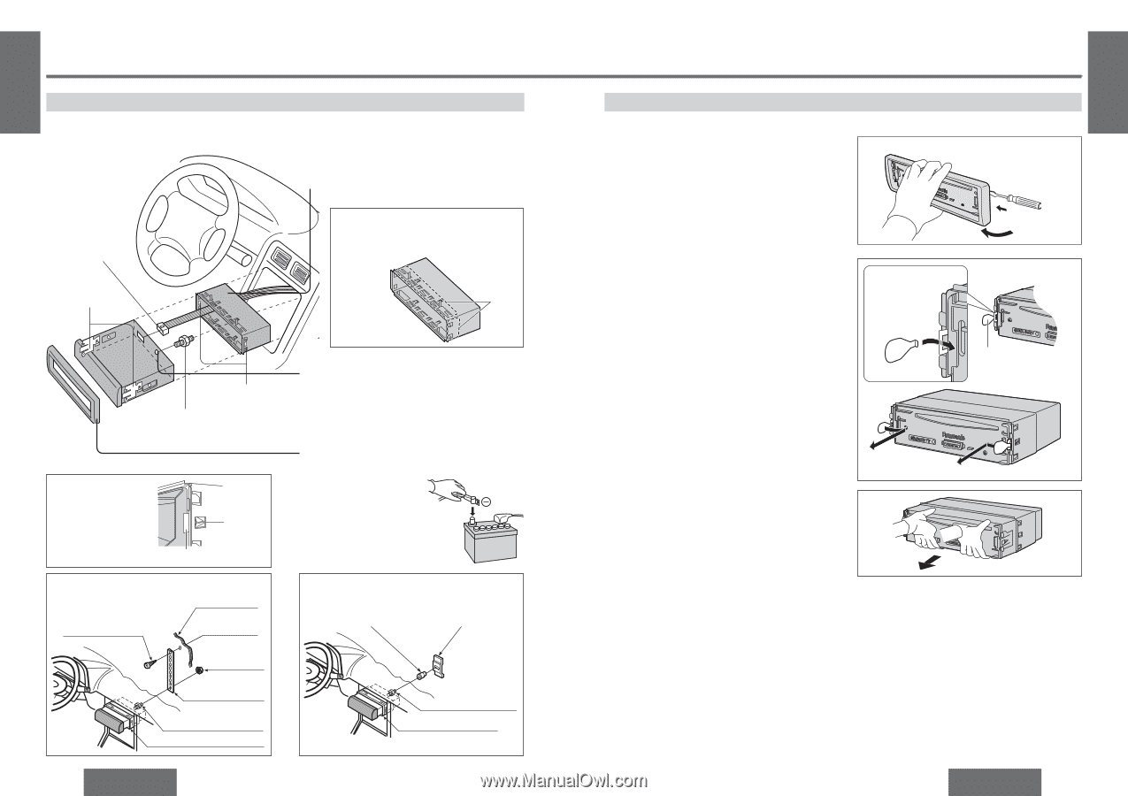
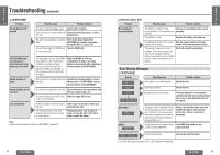
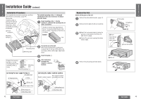
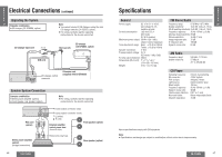
E N G Installation Guide (continued) L I S H Installation Procedures 29 First complete the electrical connections, and then check them for correctness. (page 44) Remove the mounting collar 1 and the trim plate 7 from the main unit temporarily, which are already mounted at shipment. 6 Power connector The included mounting collar 1 is designed specifically for this unit. Do not use it to attach any other model. 1 Insert mounting collar 1 into the dashboard, and bend the mounting tabs out with a screwdriver. The tabs to be bent vary depending on the car. To securely install the unit, fully bend a number of the tabs so that there is no rattling. Mounting springs (§) Example: Tab Mounting holes 5 Mounting bolt Engage the mounting springs (§) in the mounting holes of the mounting collar 1 firmly. Mounting hole Mounting springs (§) 2 Secure the rear of the unit. After fixing mounting bolt 5 and power connector 6, fix the rear of the unit to the car body by either method (a) or (b) shown below. 3 Insert trim plate 7. 4 After installation, reconnect the negative - battery terminal. (a) Using the rear support strap 3 Fire wall of car 4 Tapping screw 3 mm· (b) Using the rubber cushion (option) Rear support bracket Rubber cushion (option) (provided on the car) 2 Hex. nut 3 Rear support strap 5 Mounting bolt 1 Mounting collar 5 Mounting bolt 1 Mounting collar 42 CQ-C1300U Remove the Unit Switch off the power of the unit. 1 Remove the removable face plate. (page 37) 2 Remove the trim plate 7 with a screwdriver. 3 1 Insert the lock cancel plates 8 along the grooves on both sides of the main unit until "click" is heard. 2 Pull out the unit while pushing the plates further inside. E N G L I S H 30 7 Trim plate Screwdriver 1 2 1 Insert. Insert the tab end in the outer groove. "Click" 8 Lock cancel plate 4 Remove the unit pulling with both hands. 2 Pull out. CQ-C1300U 43
-
 1
1 -
2
-
3
-
4
-
5
-
6
-
7
-
8
-
9
-
10
-
11
-
12
-
 13
13 -
 14
14 -
 15
15 -
 16
16 -
 17
17 -
 18
18 -
 19
19 -
 20
20 -
 21
21
 |
 |