Panasonic FV08VF2 Installation Instructions - Page 11
Installation, Between, Joist, Mounting, Continued
 |
View all Panasonic FV08VF2 manuals
Add to My Manuals
Save this manual to your list of manuals |
Page 11 highlights
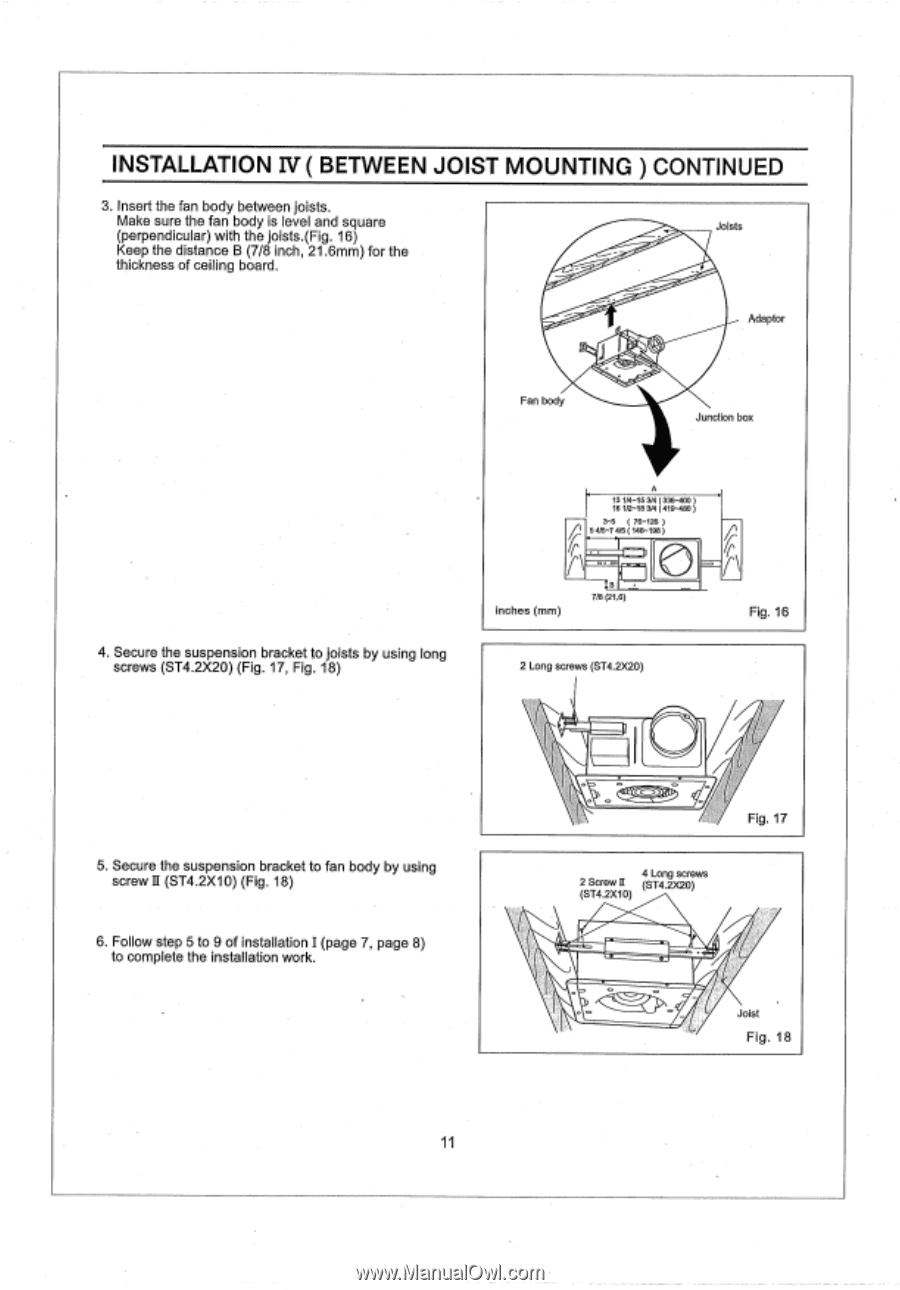
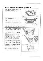
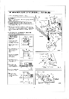
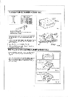
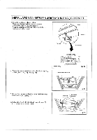
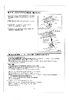
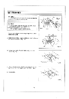
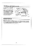
INSTALLATION IV ( BETWEEN JOIST MOUNTING ) CONTINUED 3, Insert the fan body between joists. Make sure the fan body is level and square Joists (perpendicular) with the joists.(Fig. 16) Keep the distance B (7/8 inch, 21.6mm) for the thickness of ceiling board. j Fan body Adaptor Junction box 4. Secure the suspension bracket to joists by using long screws (ST4.2X20) (Fig. 17, Fig. 18) A 13 1/4-153/4 (336-400) 18 1r2-18 3/4 (419-480) 3-5 ( 76-126 ) 5 4/5-7 4/5 ( 148-198 ) inches (mm) 38 7/8 (21 6) 2 Long screws (ST4.2X20) Fig. 16 5. Secure the suspension bracket to fan body by using screw II (ST4.2X10) (Fig. 18) 6. Follow step 5 to 9 of installation I (page 7, page 8) to complete the installation work. 11 Fig. 17 4 Long screws 2 Screw II (ST4.2X20) (ST4.2X10) Joist Fig. 18
-
 1
1 -
2
-
3
-
4
-
5
-
 6
6 -
 7
7 -
 8
8 -
 9
9 -
 10
10 -
 11
11 -
 12
12 -
 13
13 -
 14
14 -
 15
15
 |
 |