Panasonic FV08VF2 Installation Instructions - Page 8
disconnect
 |
View all Panasonic FV08VF2 manuals
Add to My Manuals
Save this manual to your list of manuals |
Page 8 highlights
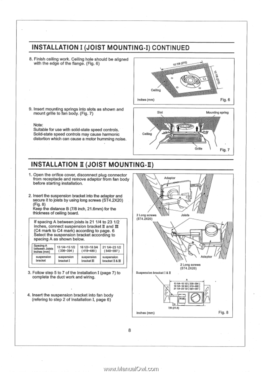
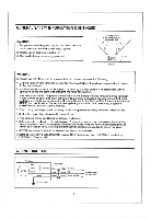
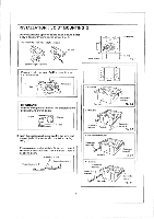
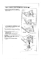
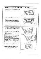
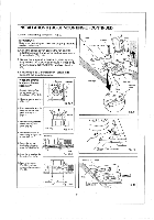
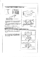
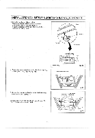
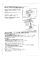
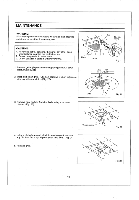
INSTALLATION I (JOIST MOUNTING-I) CONTINUED 8. Finish ceiling work. Ceiling hole should be aligned with the edge of the flange. (Fig. 6) 107/8(27 9. Insert mounting springs into slots as shown and mount grille to fan body. (Fig. 7) 7 Ceiling inches (mm) Slot (irk \ \ Fig. 6 Mounting spring Note: Suitable for use with solid-state speed controls. Solid-state speed controls may cause harmonic distortion which can cause a motor humming noise. Ceiling g.#1 • Grille Fig. 7 INSTALLATION II (JOIST MOUNTING-II) 1. Open the orifice cover, disconnect plug connector from receptacle and remove adaptor from fan body before starting installation. Adaptor 2. Insert the suspension bracket into the adaptor and secure it to joists by using long screws (ST4.2X20) (Fig. 8) Keep the distance B (7/8 inch, 21.6mm) for the thickness of ceiling board. If spacing A between joists is 21 1/4 to 23 1/2 inches, connect suspension bracket II and III (C4 mark to C4 mark) according to page. 6 Select the suspension bracket according to spacing A as shown below. Spacing A between Joists inches (mm) suspension bracket 13 1/4-15 1/2 ( 336-394 ) suspension bracket I 161/2-18 3/4 ( 419-480 ) suspension bracket M 21 1/4-23 1/2 ( 540-597 ) suspension bracket II & III 3. Follow step 5 to 7 of the Installation I (page 7) to complete the duct work and wiring. 4. Insert the suspension bracket into fan body (refering to step 2 of Installation I, page 6) 2 Long screws \ (ST4.2X20) Joists Adaptor Suspension bracket I & II 2 Long screws (ST4.2X20) inches (mm) A 13 1/4-15 1/2 ( 336-394 ) 16 1/2-18 3/4 ( 419-480) 21 1/4-23 1/2 ( 540-597 ) r\ 8 7/8 (21,6) Fig. 8 8
-
 1
1 -
2
-
 3
3 -
 4
4 -
 5
5 -
 6
6 -
 7
7 -
 8
8 -
 9
9 -
 10
10 -
 11
11 -
 12
12 -
 13
13 -
14
-
15
 |
 |