Panasonic FV08VF2 Installation Instructions - Page 7
ST4.2X20
 |
View all Panasonic FV08VF2 manuals
Add to My Manuals
Save this manual to your list of manuals |
Page 7 highlights
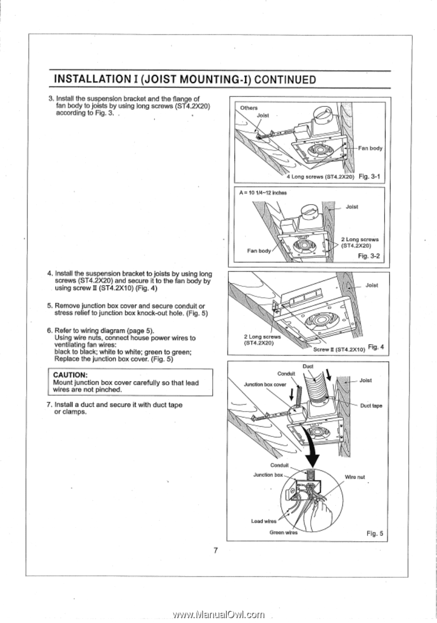
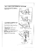
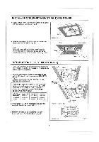
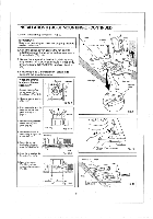
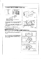
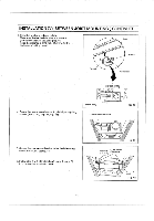
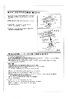
INSTALLATION I (JOIST MOUNTING-I) CONTINUED 3. Install the suspension bracket and the flange of fan body to joists by using long screws (ST4.2X20) according to Fig. 3, , Others Joist CD Fan body 4 Long screws (ST4.2X20) Fig. 3-1 A = 10 1/4-12 inches Joist 4. Install the suspension bracket to joists by using long screws (ST4.2X20) and secure it to the fan body by using screw II (ST4.2X10) (Fig. 4) 5. Remove junction box cover and secure conduit or stress relief to junction box knock-out hole. (Fig. 5) 6. Refer to wiring diagram (page 5). Using wire nuts, connect house power wires to ventilating fan wires: black to black; white to white; green to green; Replace the junction box cover. (Fig. 5) CAUTION: Mount junction box cover carefully so that lead wires are not pinched. 7. Install a duct and secure it with duct tape or clamps. Fan body 2 Long screws > (ST4.2X20) Fig. 3-2 Joist 2 Long screws (ST4.2X20) O CD 0 Screw D(ST4.2X10) Fig. 4 Conduit Junction box cover Duct - Joist Duct tape CD Conduit Junction box Wire nut Lead wires Green wires 7 Fig. 5
-
 1
1 -
 2
2 -
 3
3 -
 4
4 -
 5
5 -
 6
6 -
 7
7 -
 8
8 -
 9
9 -
 10
10 -
 11
11 -
 12
12 -
13
-
14
-
15
 |
 |