Panasonic GPUS932CUS GPUS932CU User Guide - Page 11
GP-US932CUS, <Rear>, The value is for GP-US932CUE/GP-US932CUSE.
 |
View all Panasonic GPUS932CUS manuals
Add to My Manuals
Save this manual to your list of manuals |
Page 11 highlights
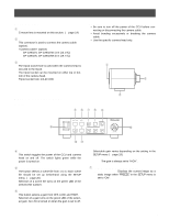
q GP-US932CU, GP-US932CUE !4 !5 !6 !3 VIDEO SYNC OUT IN ON 1234 OFF 1 SD 2 INTER. 3 NOT USE 4 RS-232C ON HD PROGRE. NOT USE FRONT SW RGB/YPb P r S-VIDEO RS-232C DC 12V IN !7 @1 @0 !9 !8 q GP-US932CUS, GP-US932CUSE !4 !5 !6 1 SDI 2 VIDEO SYNC OUT IN ON 1234 OFF 1 SD 2 INTER. 3 NOT USE 4 RS-232C ON HD PROGRE. NOT USE FRONT SW !7 RGB/YPb P r S-VIDEO RS-232C DC 12V IN @2 @1 @0 !9 !8 !3 HDMI output connector [HDMI] (* only for GPUS932CU, GP-US932CUE) This connector is used when an HDMI-ready monitor is connected. !4 Video output connector [VIDEO] This connector provides composite video signals (1.0 V[P-P], 75 ohms). !5 Synchronizing signal output/input connector [SYNC] When an external device is synchronized, set the synchronizing signal output/input selection switch !6 to "IN" to provide the synchronizing signal input. When the synchronizing signal output/input selection switch !6 is set to "OUT", the connector provides the synchronizing signal output conformable to the video format of this system. Important: • The video format shall be the same among the synchronized devices. !6 Synchronizing signal output/input selection switch [OUT/IN] This switch toggles synchronizing signals between output and input. When the synchronizing signal output is selected, set this switch to "OUT". When the synchronizing signal input is selected, set this switch to "IN". !7 Function setup switches These switches select a video format for RGB/YPbPr output connector, SDI output connector, and HDMI output connector. Switch 1 2 3 4 OFF SD (SD signal output) INTER. (Interlace output) NOT USE (Not used) RS-232C (RS-232C control) ON HD (HD signal output) PROGRE. (Progressive output) NOT USE (Not used) FRONT SW (Button operation via front face) Video format 1 080i 720p 480p (576p*) 480i (576i*) Switch 1 2 ON OFF ON ON OFF ON OFF OFF RGB/YPb SDI Pr output output b b b b b X b b HDMI output b b b X X: No output is provided. * The value is for GP-US932CUE/GP-US932CUSE. Note: • When the RS-232C port is used, set Switch 4 to "OFF" after turning off the power. When Switch 4 is set to "OFF", button operations on the front face are disabled. 11
-
 1
1 -
2
-
3
-
4
-
5
-
 6
6 -
 7
7 -
 8
8 -
 9
9 -
 10
10 -
 11
11 -
 12
12 -
 13
13 -
 14
14 -
 15
15 -
 16
16 -
17
-
18
-
19
-
20
-
21
-
22
-
23
-
24
-
25
-
26
-
27
-
28
-
29
-
30
-
31
-
32
 |
 |
