Panasonic GPUS932CUS GPUS932CU User Guide - Page 22
CHROMA GAIN], Adjusts chroma gain., TOTAL PED], Adjusts the pedestal level., USER default, B-Mg, Mg
 |
View all Panasonic GPUS932CUS manuals
Add to My Manuals
Save this manual to your list of manuals |
Page 22 highlights
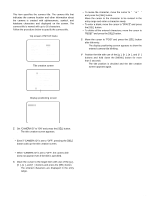
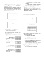
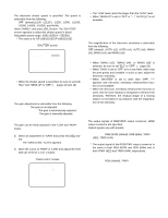
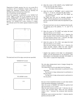
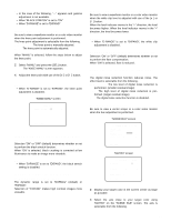
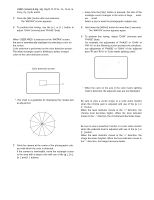
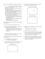
USER (default),B-Mg, Mg, Mg-R, R, R-Ye, Ye, Ye-G, G, G-Cy, Cy, Cy-B, and B c Press the [SEL] button after axis selection. → The "MATRIX" screen appears. v To perform fine tuning, use the [e] or [f] button to adjust "GAIN" (chroma) and "PHASE" (hue). When the color axis is unclear When "USER AREA" is selected on the "MATRIX" screen, the axis is automatically displayed by selecting a color on the screen. Color selection is performed on the color detection screen. The white rectangle cursor is blinking to select a target color on the color detection screen. Color detection screen R-Ye Note: • Every time the [SEL] button is pressed, the size of the rectangle cursor changes in the order of large → medium → small. Select a size to meet the photographic subject size. x Hold down the [MENU] button for more than 2 seconds. → The "MATRIX" screen appears again. c To perform fine tuning, adjust "GAIN" (chroma) and "PHASE" (hue). For example, the adjustment of "PHASE" or "GAIN" of "R/R-Ye" on the following screen provides the simultaneous adjustment of "PHASE" or "GAIN" of the adjacent axes "R" and "R-Ye" in "Color matrix splitting chart". ** MATRIX ** USER R/R-Ye PHASE -....|....+ R PHASE -....|....+ R-Ye PHASE -....|....+ R/R-Ye GAIN -....|....+ R GAIN -....|....+ R-Ye GAIN -....|....+ USER AREA * RET END Cursor (Blinking) * This chart is a guideline for displaying the closest axis at adjustment. R-Ye R Mg-R Mg Ye B-Mg Ye-G B G G-Cy Cy Cy-B z Point the camera at the center of the photographic sub- ject with which the color is detected. If the camera is immovable, move the rectangle cursor to the area with a target color with use of the [g], [h], [e], and [f] buttons. Note: • When the color on the axis in the color matrix splitting chart is detected, the adjacent axes are not displayed. [CHROMA GAIN] Adjusts chroma gain. Be sure to view a vector scope or a color video monitor when the chroma gain is adjusted with use of the [e] or [f] button. When the level indicator moves in the "+" direction, the chroma level becomes higher. When the level indicator moves in the "-" direction, the chroma level becomes lower. [TOTAL PED] Adjusts the pedestal level. Be sure to view a waveform monitor or a color video monitor when the pedestal level is adjusted with use of the [e] or [f] button. When the level indicator moves in the "+" direction, the image becomes brighter. When the level indicator moves in the "-" direction, the image becomes darker. 22
-
 1
1 -
2
-
3
-
4
-
5
-
6
-
7
-
8
-
9
-
10
-
11
-
12
-
13
-
14
-
15
-
16
-
 17
17 -
 18
18 -
 19
19 -
 20
20 -
 21
21 -
 22
22 -
 23
23 -
 24
24 -
 25
25 -
 26
26 -
 27
27 -
28
-
29
-
30
-
31
-
32
 |
 |
