Panasonic PTDW5100 User Manual - Page 33
Input Resolution, Clamp Position, Edge Blending
 |
View all Panasonic PTDW5100 manuals
Add to My Manuals
Save this manual to your list of manuals |
Page 33 highlights
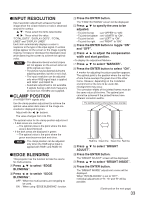
INPUT RESOLUTION Input resolution adjustment achieves the best image when the screen flickers or halo is observed around the contour. : These select the items listed below. : These select the value. "TOTAL DOTS", "DISPLAY DOTS", "TOTAL LINES" and "DISPLAY LINES" Each item automatically displays a value in response to the type of the input signal. If vertical stripes appear on the screen or the image is partly missing, increase or decrease the displayed value while observing the screen to achieve the optimal value. Note • The abovementioned vertical stripes will not appear on the screen when all white signals are input. • The picture may be distorted during the adjusting operation, but this is not a fault. • The input resolution can be adjusted only when RGB signal input is applied with RGB1 and RGB2 IN. • Automatic adjustment is not available if signals having a dot clock frequency of more than 150 MHz are supplied. CLAMP POSITION (For RGB/YPBPR signals only) Use the clamp position adjustment to achieve the optimal value when dark areas of the image are crushed or displayed in green. Adjust with the buttons. The value changes from 0 to 255. The optimal value for the clamp position adjustment • If dark areas are crushed: The optimal value is the point where the dark area is best improved. • If the dark areas are displayed in green: The optimal value is the point where the green area becomes dark and clear. Note • The clamp position can be adjusted only when the RGB signal input is applied with RGB1 and RGB2 IN. EDGE BLENDING This projector has the function to hide the seams for multi-screens. Press to select "EDGE BLENDING". Press to switch "EDGE BLENDING". OFF : When the multi-screens are not going to be used. ON : When using "EDGE BLENDING" function. Press the ENTER button. The "EDGE BLENDING" screen will be displayed. Press to specify the area to be adjusted. • To joint the top : set "UPPER" to "ON". • To joint the bottom : set "LOWER" to "ON". • To joint the left : set "LEFT" to "ON". • To joint the right : set "RIGHT" to "ON". Press the ENTER button to toggle "ON" and "OFF". Press to adjust the compensation width and start position. Press to select "MARKER". Press the ENTER button to select "ON". A marker for adjusting the picture position appears. The optimal point is the position where the red line of one frame overlaps the green line of the other frame. However, depending on the installation environment or the lens to be used, dotmisalignment may occur. The correction widths of the jointed frames must be the same value all the time. The optimal joint cannot be achieved if the jointed frames have different correction widths. The optimal point is where these lines overlap. Red line Green line Green line Red line Press to select "BRIGHT ADJUST". Press the ENTER button. The "BRIGHT ADJUST" screen will be displayed. Press to select "BRIGHT INSIDE". Press the ENTER button. The "BRIGHT INSIDE" adjustment screen will be displayed. When "INTERLOCKED" is set to "OFF", individual adjustment of "R", "G" and "B" will be possible. (Continued on the next page) 33
-
 1
1 -
2
-
3
-
4
-
5
-
6
-
7
-
8
-
9
-
10
-
11
-
12
-
13
-
14
-
15
-
16
-
17
-
18
-
19
-
20
-
21
-
22
-
23
-
24
-
25
-
26
-
27
-
 28
28 -
 29
29 -
 30
30 -
 31
31 -
 32
32 -
 33
33 -
 34
34 -
 35
35 -
 36
36 -
 37
37 -
 38
38 -
39
-
40
-
41
-
42
-
43
-
44
-
45
-
46
-
47
-
48
-
49
-
50
-
51
-
52
-
53
-
54
-
55
-
56
-
57
-
58
-
59
-
60
-
61
-
62
-
63
-
64
-
65
-
66
-
67
-
68
-
69
-
70
-
71
-
72
 |
 |
