Panasonic SAHT730 Technical Guide - Page 11
Testing the Tray Rotation Motor and Related Sensors - sa ht730 parts
 |
View all Panasonic SAHT730 manuals
Add to My Manuals
Save this manual to your list of manuals |
Page 11 highlights
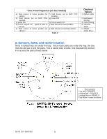
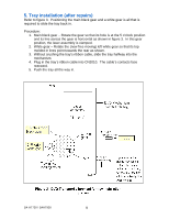
Testing the Tray Rotation Motor and Related Sensors 1. With the tray removed, install the front panel to begin the remaining tests. 2. Place the plastic tray on top of the unit between the laser block and front panel. 3. Plug the tray ribbon cable into CN2010 for testing. Part 4. Tray rotation motor 5. Tray M rotation sensor S9102 6. Tray position sensor Q9101 7. Disc presence detector Q9103 Setup Press the power on button. Press the power on button. Press the power on button. Press the power on button. Testing Parts 2/2 Do / Watch Tray motor should turn 8 seconds after the power button is pressed. Rotate the tray motor gear by hand. Before the unit shuts down, rotate the tray past the disc center position at the laser assembly. Move the tray past the disc sensor. Table 5 Proof the part is good Power to tray motor: Pin 11 = gnd. Pin 10 will go from 0 - 2V - 5.6Vdc. At CN2010/pin 4: Voltage changes from 0.1Vdc to 4.6Vdc as the tray gear is turned. Volts at CN2010/pin 2: 0.15Vdc = Tray centered for disc playback. 5Vdc. = Tray in transit. At CN2010/pin 6: 0.3Vdc = light reflected back from top plate. 5Vdc = light blocked To CN2010 Motor: pin 11 = gnd. Pin 10 = 0V, 2V, 5.6V 3.6Vdc CN2010/Pin 6: 5.0V = Disc 0.3V = No Disc Pin 4: motor rot. 0.1V to 4.6Vdc Figure 5 - Tray Rotation circuit CN2010/Pin 2: 0.15 = disc centered 5Vdc = tray bet discs. SA-HT730 / SAHT930 11
-
 1
1 -
2
-
3
-
4
-
5
-
 6
6 -
 7
7 -
 8
8 -
 9
9 -
 10
10 -
 11
11 -
 12
12 -
 13
13 -
 14
14 -
 15
15 -
 16
16 -
17
-
18
-
19
-
20
-
21
-
22
-
23
 |
 |
