Panasonic SAHT730 Technical Guide - Page 12
Shutdown Problem - model sa ht730
 |
View all Panasonic SAHT730 manuals
Add to My Manuals
Save this manual to your list of manuals |
Page 12 highlights
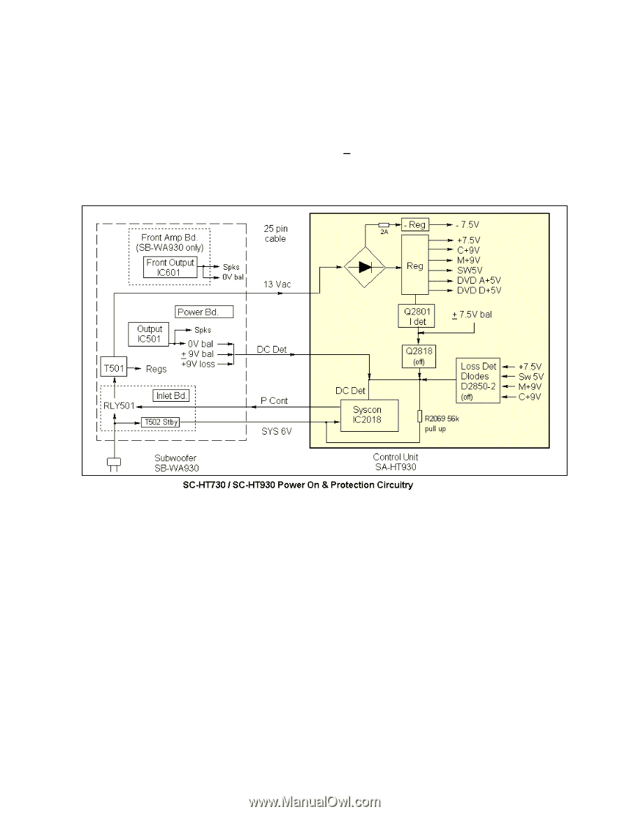
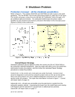
II Shutdown Problem Protection Concept - all the shutdown possibilities Refer to figure 6. The models SCHT730 and SCHT930 are both 2-piece units (with speakers). The SA-HT930 / SA-HT730 control piece (figure 6, right) has no AC input. The control unit power comes from the SB-WA 30 "Subwoofer" piece through a 25 pin umbilical cable (not shown). The subwoofer (left) houses the power output amplifier for all 6 channels and delivers protection information to the microprocessor (Syscon IC2018) in the control unit. Figure 6 - Overall Repair Strategy Shutdown protection can be started in either the control unit (SA-HT730/HT930) or the subwoofer (SB-WA730/WA930). Start the repair with either unit to first determine which piece houses the problem, and then follow the individual Repair Strategy procedure to isolate the problem. Control Unit - In the control unit, most parts are under the board. Access to test areas for diagnosis is overcome by using the jumper wires on the top as test points. Since test point jumpers are used, additional diagrams and pictures are used to quickly locate the jumpers. The repair flow information is shown in figure 7. Control unit repair starts on page 13. Subwoofer Unit - All parts are accessible once the electronics is pulled from the subwoofer speaker cabinet. Unscrewing the board from the metal frame and rotating it 90 degrees permits operation if a ground wire is added (service position). Subwoofer unit repair starts on page 17. SA-HT730 / SAHT930 12
-
 1
1 -
2
-
3
-
4
-
5
-
6
-
 7
7 -
 8
8 -
 9
9 -
 10
10 -
 11
11 -
 12
12 -
 13
13 -
 14
14 -
 15
15 -
 16
16 -
 17
17 -
18
-
19
-
20
-
21
-
22
-
23
 |
 |