Panasonic SAHT730 Technical Guide - Page 14
Control unit repair Procedure
 |
View all Panasonic SAHT730 manuals
Add to My Manuals
Save this manual to your list of manuals |
Page 14 highlights
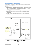
Control unit repair Procedure To perform the following steps, you need to locate the jumper wires and identify which jumpers carry what shutdown signals to the IC2018 microprocessor (using figure 9). The purpose of the jumpers is found in the concept diagram figure 10. Procedure: 1. First prove the problem is in the control unit by cutting the W2344 jumper on the top of the board (at location grid K7). Measure the voltage at W2156 / G8 at power on. This cut disconnects most of the control unit's protection into micro IC2018. • If the 9Vdc is present before shutdown, the problem is in the subwoofer assembly and not in the control unit. Reconnect the jumper and go to the repair information on the subwoofer (page 12). • If the 9Vdc is present, and the unit does not shutdown the problem is in the control unit. Shut off the unit and proceed to step 2. • If the 9Vdc is absent, the problem is in the control unit. Refer to figures 9 and 10. Either the M9V source (Q2803) is missing or the 9Vdc is loaded down (reduced). Cut jumpers W2413 and W2154 one at a time to determine which load causes the reduced or missing voltage. If cutting both jumpers does not restore the missing 9V, the M+9V source is bad. 2. If the unit does not shutdown because you have compromised the protection circuit (e.g. cut W2344), only keep the unit on to measure a test voltage. Monitor the various voltages at these jumpers to determine which is incorrect: [The jumper's grid location follows the "W" jumper number.] + W2550 / M7 = SW 5Vdc W2417 / K8 = + 7Vdc W2340 / I7 = - 7Vdc W2235 / K9 = 0Vdc W2427 / J8 = 9Vdc Inv Q2818 IC2018 Micro 3. Except for the K9 (0V) measurement, if any of the voltages listed above is missing, cut the (load) jumper and measure each of its ends. If the voltage is now present at one end after the cut, its load is shorted. Trace down and troubleshoot the Use the "Protect Paths to Micro IC2018" diagram (figure 9) to make sure that the jumper is the load jumper that bridges the load and the source voltage before cutting. SA-HT730 / SAHT930 14
-
 1
1 -
2
-
3
-
4
-
5
-
6
-
7
-
8
-
 9
9 -
 10
10 -
 11
11 -
 12
12 -
 13
13 -
 14
14 -
 15
15 -
 16
16 -
 17
17 -
 18
18 -
 19
19 -
20
-
21
-
22
-
23
 |
 |
