Panasonic WJ-HD616/1000 Installation Guide - Page 37
Cascading connection of multiple recorders
 |
View all Panasonic WJ-HD616/1000 manuals
Add to My Manuals
Save this manual to your list of manuals |
Page 37 highlights
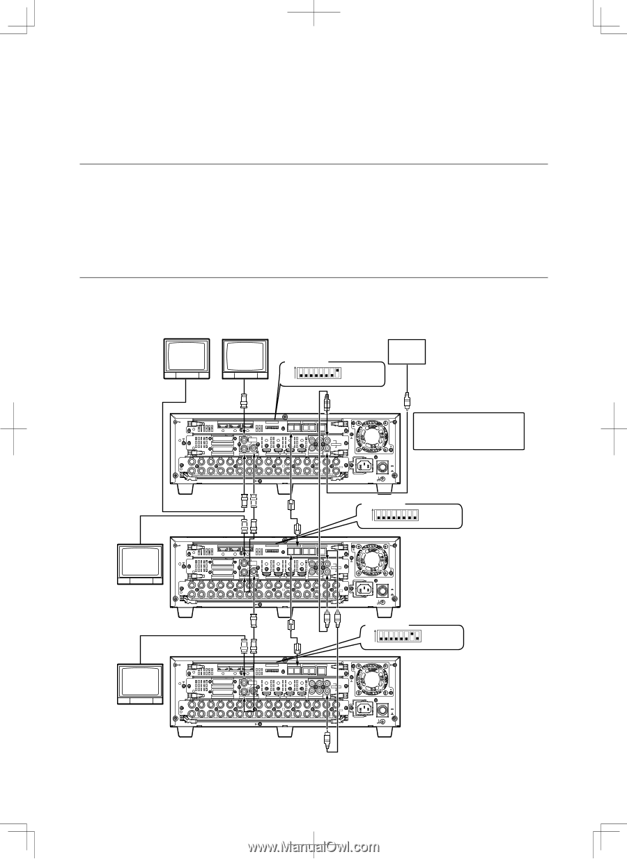
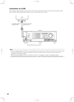
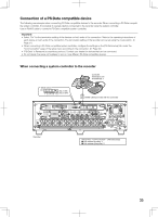
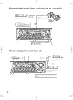
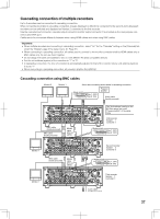
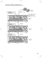
Cascading connection of multiple recorders Up to 5 recorders can be connected in cascading connection. When connecting recorders in cascading connection, images displayed on Monitor 2 connected to the second and subsequent recorders can be switched and displayed on Monitor 2 connected to the first recorder. Use the cascade input connector, cascade output connector (monitor output connector 2 is provided as the dual purpose connector) and DATA port. Cables are to be connected differently between when using HDMI cables and when using BNC cables. Important: • When multiple recorders are connecting in cascading connection, select "On" for the "Cascade" setting on the [Cascade] tab under the "Display" page of the setup menu. (☞ Page 91) • When connecting in cascading connection, all cables used to connect to the monitor connector shall be HDMI cables only or BNC cables only. Do not use them together. • Do not assign the same unit address to two or more different PS·Data compatible devices. • Set the unit address (system) of the recorders to "1" to "5". • In cascading connection, the time of recorders is automatically adjusted to that of the recorder whose unit address (system) is set to "1". • When connecting in cascading connection, all recorders shall be WJ-HD616K. Cascading connection using BNC cables Monitor 2 Monitor 1 * When also connecting audio cables in cascading connection Mode switch ON (No.7: OFF) 1 2 3 4 5 6 7 8 (No.8: ON) Powered speaker Audio cable (locally procured) Monitor 1 Monitor 1 IN OUT EXT STORAGE MODE DATA RS485(CAMERA) 10/100BASE-T 3 2 ALARM ALARM/CONTROL 1 1 MONITOR OUT 2 OUT-CASCADE-IN 12345678 2 2 1 2 1 CASCADE IN OUT MONITOR OUT(HD) 1 3 1 IN CASCADE OUT 4 2 AUDIO AUDIO IN OUT 16 15 14 13 12 11 10 9 8 7 6 5 4 3 2 1 7 1 OUT 16 15 14 13 12 11 10 9 8 7 6 5 4 3 2 VIDEO POWER ON OFF AC IN SIGNAL GND The "Unit address" setting on the [PS·Data setup] tab under "Communication" of the setup menu First recorder System: 1 Controller: 1 BNC cable (locally procured) BNC cable (locally procured) RS485 cable (WV-CA 48/50) IN OUT EXT STORAGE MODE DATA RS485(CAMERA) 10/100BASE-T 3 2 ALARM ALARM/CONTROL 1 1 MONITOR OUT 2 OUT-CASCADE-IN 12345678 2 2 1 2 1 CASCADE IN OUT MONITOR OUT(HD) 1 3 1 IN CASCADE OUT 4 2 AUDIO AUDIO IN OUT 16 15 14 13 12 11 10 9 8 7 6 5 4 3 2 1 7 1 OUT 16 15 14 13 12 11 10 9 8 7 6 5 4 3 2 VIDEO Mode switch ON (No.7: OFF) (No.8: OFF) 123456 78 POWER ON OFF AC IN SIGNAL GND Second recorder System: 2 Controller: 2 BNC cable (locally procured) RS485 cable (WV-CA 48/50) Mode switch ON (No.7: OFF) 1 2 3 4 5 6 7 8 (No.8: ON) IN OUT EXT STORAGE MODE DATA RS485(CAMERA) 10/100BASE-T 3 2 ALARM ALARM/CONTROL 1 1 MONITOR OUT 2 OUT-CASCADE-IN 12345678 2 2 1 2 1 CASCADE IN OUT MONITOR OUT(HD) 1 3 1 IN CASCADE OUT 4 2 AUDIO AUDIO IN OUT 16 15 14 13 12 11 10 9 8 7 6 5 4 3 2 1 7 1 OUT 16 15 14 13 12 11 10 9 8 7 6 5 4 3 2 VIDEO POWER ON OFF AC IN SIGNAL GND Third recorder System: 3 Controller: 3 Audio cable (locally procured) 37
-
 1
1 -
2
-
3
-
4
-
5
-
6
-
7
-
8
-
9
-
10
-
11
-
12
-
13
-
14
-
15
-
16
-
17
-
18
-
19
-
20
-
21
-
22
-
23
-
24
-
25
-
26
-
27
-
28
-
29
-
30
-
31
-
 32
32 -
 33
33 -
 34
34 -
 35
35 -
 36
36 -
 37
37 -
 38
38 -
 39
39 -
 40
40 -
 41
41 -
 42
42 -
43
-
44
-
45
-
46
-
47
-
48
-
49
-
50
-
51
-
52
-
53
-
54
-
55
-
56
-
57
-
58
-
59
-
60
-
61
-
62
-
63
-
64
-
65
-
66
-
67
-
68
-
69
-
70
-
71
-
72
-
73
-
74
-
75
-
76
-
77
-
78
-
79
-
80
-
81
-
82
-
83
-
84
-
85
-
86
-
87
-
88
-
89
-
90
-
91
-
92
-
93
-
94
-
95
-
96
-
97
-
98
-
99
-
100
-
101
-
102
-
103
-
104
-
105
-
106
-
107
-
108
-
109
-
110
-
111
-
112
-
113
-
114
-
115
-
116
-
117
-
118
-
119
-
120
-
121
-
122
-
123
-
124
-
125
-
126
-
127
-
128
-
129
-
130
-
131
-
132
-
133
-
134
-
135
-
136
-
137
-
138
-
139
-
140
-
141
-
142
-
143
-
144
-
145
-
146
-
147
-
148
-
149
-
150
-
151
-
152
-
153
-
154
-
155
-
156
 |
 |