Panasonic WVNS202A WVNS202A User Guide - Page 16
Step 7, Recommended tightening torque, Important, Network connector, DC 12 V power terminals - pan
 |
View all Panasonic WVNS202A manuals
Add to My Manuals
Save this manual to your list of manuals |
Page 16 highlights
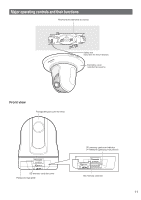
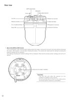
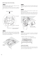
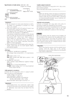
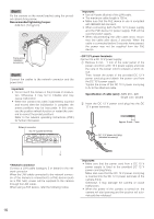
Step 7 Fix the camera on the mount bracket using the provided camera fixing screw. Recommended tightening torque: 0.68 N·m {7.0 kgf·cm} Fixing screw (standard accessory) Step 8 Connect the cables to the network connector and the power inlet. Important: • Do not touch the camera in the process of initializa- tion. Otherwise, it may fail to initialize and may cause malfunction. • When the camera has been inadvertently touched and moved after the initialization is complete, the preset positions may be inaccurate. In this case, use the position refresh function or restart the camera to correct the preset positions. Refer to the network operating instructions (PDF) for further information. Network connector DC 12 V power terminals 10BASE-T/ 100BASE-TX LINK ACT INITIAL SET POWER 4 3 2 1 MIC IN AUDIO OUT MONITOR OUT 12V IN EXT I/O Important: • Use all 4 pairs (8 pins) of the LAN cable. • The maximum cable length is 100 m. • Make sure that the PoE device in use is compliant with IEEE802.3af standard. • When connecting both the DC 12 V power supply and the PoE device for power supply, PoE will be used for power supply. • When disconnecting the LAN cable once, reconnect the cable after about 2 seconds. When the cable is connected before 2 seconds have passed, the power may not be supplied from the PoE device. • DC 12 V power terminals Connect to a DC 12 V power supply. q Remove 3 mm - 7 mm of the outer jacket of the power cord from a DC 12 V power supply and twist the core of the power cord to prevent a short circuit. Then, loosen the screw of the provided DC 12 V power cord plug and attach the power cord from the DC 12 V power supply. Tighten the screw of the DC 12 V power cord plug to fix to the attached cable. Specification of cable (wire): AWG #16 - #28 Single core, twisted w Insert the DC 12 V power cord plug into the DC 12 V power terminals. Approx. 3 mm - 7 mm -+ DC 12 V power cord plug (standard accessory) + - • Network connector Connect a LAN cable (category 5 or better) to the network connector. When the LAN cable connected to the network connector of the camera is connected to a PoE device (such as a PoE hub), power will be supplied to the camera through the LAN cable. When using a PoE device, refer the following notice. Important: • Make sure that the power cord from a DC 12 V power supply is fixed to the provided DC 12 V power cord plug firmly. Make also sure that the DC 12 V power cord plug is inserted into the DC 12 V power terminals of the camera firmly. Otherwise, it may damage the camera or cause malfunction. • When the power of the camera is turned on, the camera will start panning and the position will automatically be initialized. 16
-
 1
1 -
2
-
3
-
4
-
5
-
6
-
7
-
8
-
9
-
10
-
 11
11 -
 12
12 -
 13
13 -
 14
14 -
 15
15 -
 16
16 -
 17
17 -
 18
18 -
 19
19 -
 20
20 -
 21
21 -
22
-
23
-
24
-
25
-
26
-
27
-
28
 |
 |
