Philips LC3141 Service Manual - Page 3
Mechanical instructions
 |
View all Philips LC3141 manuals
Add to My Manuals
Save this manual to your list of manuals |
Page 3 highlights
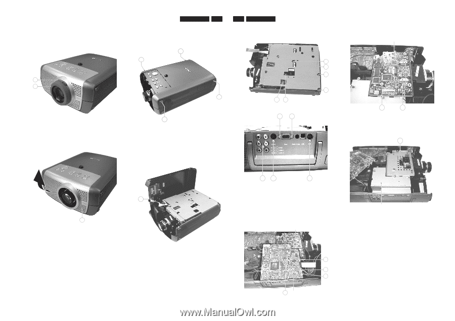
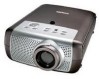
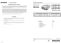
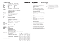
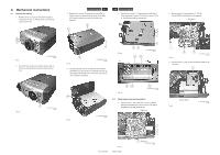
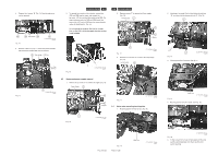
4. Mechanical instructions 4.1 Opening the cabinet 1. Remove the focus ring (A) and the zoom ring (B) by pulling them off (Fig. 1). Pulling off the zoom ring may require some force. B A Fig. 1 CL 266450004_044.eps 230402 2. Pull off the front cover (C) by pulling it upward (Fig. 2). Pulling can best be done by using the opening of the lens. Fig. 2 C CL 266450004_046.eps 240402 LC3131/LC3141 4-1 3. Remove the 4 screws (D) holing the top cover (Fig. 3). If the 4 screws are removed, the top cover can be lifted off. Please be careful not to pull of the cable to the keyboard. D D 4-2 LC3131/LC3141 5. Remove the 6 screws "F" holding the top shield (Fig. 5). Then remove the 3 screws "G" and the 2 screws "H" (Fig. 6). Now the top shield can be removed. F F F D D Fig. 3 CL 266450004_047.eps 240402 4. By putting the top cover to the side, the set can still be operated (Fig. 4). Be careful not to damage connector E. By pulling the flatfoil cable from connector E the topcover can be removed completely. Fig. 5 F F F CL 266450004_049.eps 240402 H H E Fig. 4 G G Fig. 6 G CL 266450004_050.eps 24402 CL 266450004_048.eps 240402 4.2 Panel removal and service position 1. Remove screw "I" and connectors "J" (Fig. 7). Now the SSB (Small Signal Board) can be removed. The SSB is plugged onto the DRB (Drive Board). DRB Board PCS 107 362 Fig. 7 PCS 107 363 J J J I SSB Board CL 266450004_051.eps 240402 2. Remove screw "K" and connectors "L" (Fig. 8). Nor the DRB (Drive Boards) can be removed. DRB Board Fig. 8 K L CL 266450004_052.eps 240402 3. Remove screw "L" (Fig. 9). Now the bottom shield can be removed. L Fig. 9 Bottom Shield CL 266450004_053.eps 240402
-
 1
1 -
 2
2 -
 3
3 -
 4
4 -
 5
5 -
 6
6 -
 7
7 -
 8
8 -
 9
9 -
10
-
11
-
12
-
13
-
14
-
15
-
16
-
17
-
18
-
19
-
20
-
21
-
22
-
23
-
24
-
25
-
26
-
27
-
28
-
29
-
30
-
31
-
32
-
33
-
34
-
35
-
36
-
37
-
38
-
39
-
40
-
41
-
42
-
43
-
44
-
45
-
46
-
47
-
48
-
49
-
50
 |
 |