Philips LC3141 Service Manual - Page 4
LC3131/LC3141 - 17
 |
View all Philips LC3141 manuals
Add to My Manuals
Save this manual to your list of manuals |
Page 4 highlights
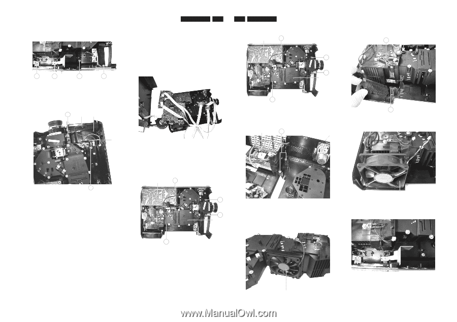
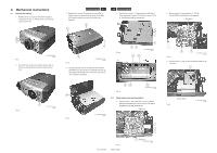
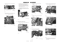
4 Remove the 4 screws "M" (Fig. 10). Now the side cover can be removed. M M Side Cover M Fig. 10 M CL 266450004_054.eps 240402 5. Remove screws "N" (Fig. 11). After lifting the fan bracket, the filter holder and dust filter can be removed. N Filter Holder LCD Fan Fan Bracket LC3131/LC3141 4-3 6. To operate the projector in this situation, connect the SSB and DRB together again, and connect the top-cover, LCD fan and dust filter switch to the SSB. Put some insulation under the SSB and DRB board. Now connect the LCD's to the DRB board by using extension cables (312243540400). (Fig. 12) Do not operate the projector like this for a longer time, as the LCD's will be damaged when the cooling is not installed. 4-4 LC3131/LC3141 2. Remove screws "P" to remove the Power supply (Fig. 13). Power Supply P O O Engine Fig. 12 CL 266450004_056.eps 230402 O Fig. 13 CL 266450004_057.eps 240402 3. Remove the 2 screws "Q" to remove the lamp supply (Fig. 14). Lamp Supply Q Fig. 11 N CL 266450004_055.eps 240402 4.3 Engine and power supply removal 1. Remove the 3 screws "O" to remove the engine (Fig. 13). Power Supply P O O Engine Fig. 14 CL 266450004_058.eps 240402 4.4 Notes when mounting back together 1. Mounting position of PCS fan (See Fig. 15). O Fig. 13 CL 266450004_057.eps 240402 2. Mounting of air guide: First put the bottom pin into hole "R", and then click the top pin into hole "S". (Fig. 16). S Fig. 16 R CL 266450004_060.eps 240402 3. Mounting position of lamp fan (See fig 17). Fig. 17 Lamp Fan CL 266450004_061.eps 240402 4. Mounting position of earth bracket. (See Fig. 18) PCS 107 364 Fig. 15 PCS 107 365 PBS Fan CL 266450004_059.eps 140502 CL 266450004_062.eps 230402 Fig. 18 5. If after a repair the fan's go to high speed and the lamp switches off immediately, then check the filter door switch mounting.
-
 1
1 -
 2
2 -
 3
3 -
 4
4 -
 5
5 -
 6
6 -
 7
7 -
 8
8 -
 9
9 -
 10
10 -
11
-
12
-
13
-
14
-
15
-
16
-
17
-
18
-
19
-
20
-
21
-
22
-
23
-
24
-
25
-
26
-
27
-
28
-
29
-
30
-
31
-
32
-
33
-
34
-
35
-
36
-
37
-
38
-
39
-
40
-
41
-
42
-
43
-
44
-
45
-
46
-
47
-
48
-
49
-
50
 |
 |