Philips LC3141 Service Manual - Page 45
Parts lists - xg1
 |
View all Philips LC3141 manuals
Add to My Manuals
Save this manual to your list of manuals |
Page 45 highlights
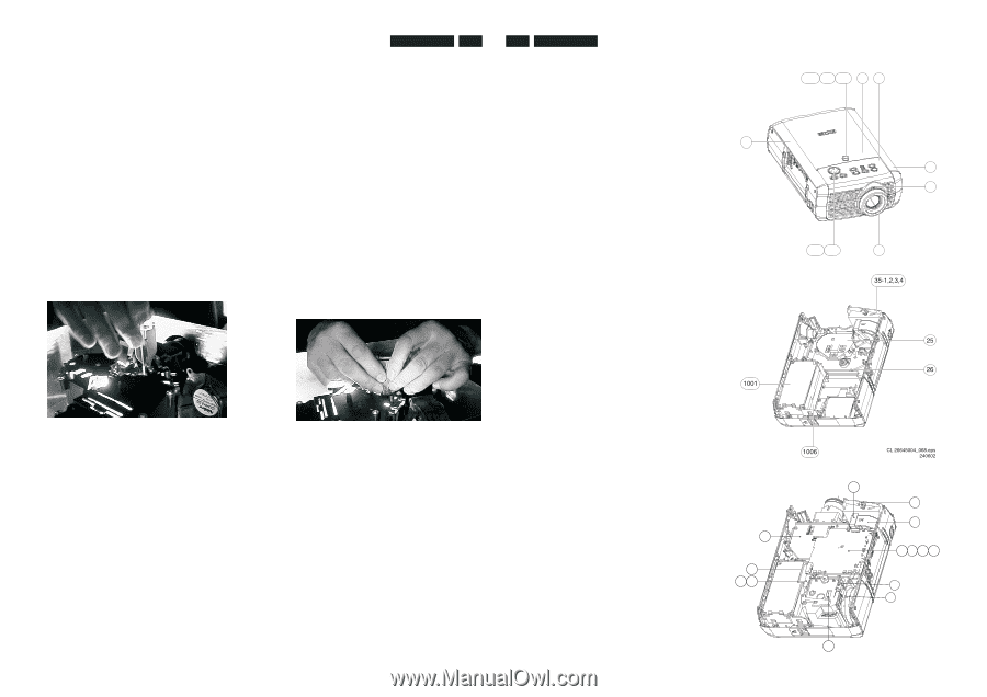
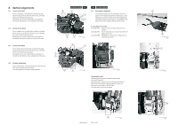
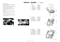
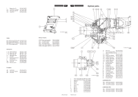
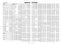
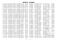
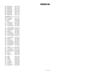
Aligning the convergence With a the key (I), the 2 screws (H) can be loosened from the top. This is a critical action: the crews have to be loosed so that the LCD can be moved with some friction. Now clamp the manipulator over the LCD panel. With the manipulator the LCD can be moved into the correct position. If the movement is too light or too difficult, readjust the tightness of screws (H). Adjustment can best be done in the following order. Lift the LCD up, so that the picture is below the original picture. Now rotate the LCD, so that the vertical lines are parallel to the vertical lines of the original. Now adjust the picture left/right, so that the sides match the sides of the original. Now carefully push the LCD panel down, keeping the sides parallel, until the picture is correct. If you do not get the required result, sometimes a small correction can be done, but otherwise it is better to start over again. If the convergence is within specification (< 1 pixel), carefully fix the screws (H), to fix the LCD. If necessary fix the LCD with some glue or lacquer, before fixing the screws. CL 26645004_086.eps 050802 LC3131/LC3141 8-3 9-1 LC3131/LC3141 Mechanical parts 9. Parts lists 2 Top Assy 3122 437 16380 2-3 IR Lens 3122 434 01750 2-4 IR Glass 3122 434 21400 2-5 Control Knobs 3122 434 21390 3 $ Front Cover Lacquered 3122 438 11850 4 Side Assy 3122 437 16390 5 IO Side Assy (complete) 3122 437 16400 11 Zoom Ring Lacquered 12 Focus Ring Assy 3122 438 11910 3122 437 16430 5 1001 Keyboard Board 3122 438 51170 1002 IR-Receiver Board 3122 438 51180 1002 2-4 2-3 2 3 4 11 25 Air Guide Assy 26 $ Bracket PS 35-1 $ Housing Dust Filter 35-2 $ Frame Dust Filter 35-3 $ Dust Filter (Foam) 35-4 Filter Retainer 1001 $ Power Supply Module 1006 $ Lamp Supply 132W SV1 1006 $ Lamp Supply 150W XG1 3122 437 16420 3122 434 01770 3122 434 01590 3122 438 11810 3122 434 01570 3122 433 70600 3122 438 00060 9137 001 48403 3122 438 71230 CL 26645004_087.eps 050802 15 $ Light Shield 19 $ Bracket Fan PCS 20 $ LCD Fan Bracket 33 Cable Retainer 1002 Drive Board SVGA Ed1 1002 Drive Board XGA Ed1 1004 Small Signal Board 1008 $ Fan Ass. S10-Main Fan 1009 $ Fan Assy S12-PCS Fan 1010 $ Fan Assy S13-LCD Fan 8001 $ Dust Filter Switch 8007 $ Temp. Switch + Cable 3122 434 21600 3122 434 01560 3122 434 01740 3122 433 70620 3122 438 50990 3122 438 51030 3122 438 51150 3122 437 51250 3122 437 51260 3122 437 51270 3122 431 01820 3122 431 01680 PCS 107 418 PCS 107 419 1001 2-5 12 CL 26645004_075.eps 120802 35-1,2,3,4 1001 25 26 1002 33 19 1009 1006 CL 26645004_068.eps 240602 20 8001 1010 1004 161 169 8003 15 1008 8007 CL 26645004_070.eps 120802
-
 1
1 -
2
-
3
-
4
-
5
-
6
-
7
-
8
-
9
-
10
-
11
-
12
-
13
-
14
-
15
-
16
-
17
-
18
-
19
-
20
-
21
-
22
-
23
-
24
-
25
-
26
-
27
-
28
-
29
-
30
-
31
-
32
-
33
-
34
-
35
-
36
-
37
-
38
-
39
-
 40
40 -
 41
41 -
 42
42 -
 43
43 -
 44
44 -
 45
45 -
 46
46 -
 47
47 -
 48
48 -
 49
49 -
 50
50
 |
 |