Philips LC3141 Service Manual - Page 44
Optical alignments - lighting
 |
View all Philips LC3141 manuals
Add to My Manuals
Save this manual to your list of manuals |
Page 44 highlights
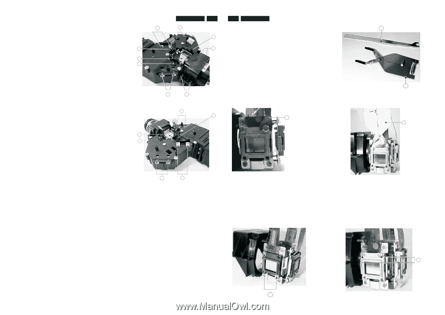
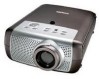
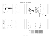
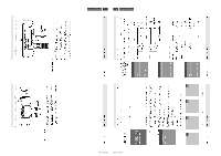
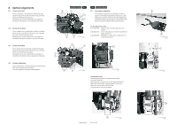
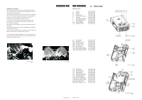
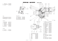
8. Optical alignments 8.1 Corner mirror Red Put on a red picture. If dark bands are visible on the sides, loosen the two screws (A) fixing the mirror on top, and move the mirror till the dark bands are gone. Alternatively you can use a white picture (LCD panels not connected), and check for a red or yellow bar at the sides. 8.2 Corner mirror Green Put on a green picture. If dark bands are visible on the sides, loosen the two screws (B) fixing the mirror on top, and move the mirror till the dark bands are gone. Alternatively you can use a white picture (LCD panels not connected), and check for a green or cyan bar at the sides. 8.3 Corner mirror Blue Put on a blue picture. If dark bands are visible on the sides, loosen the two screws (C) fixing the mirror on top, and move the mirror till the dark bands are gone. Alternatively you can use a white picture (LCD panels not connected), and check for a blue or magenta bar at the sides. 8.4 Polarizer adjustment Put on a black picture. Loosen the screw (D) on top. Move the slider bar (E) minimal light in the picture. The same adjustment is valid for all three polarizer's. LC3131/LC3141 8-1 8-2 LC3131/LC3141 B C 8.5 Convergence alignment In the standard configuration the convergence cannot be E adjusted. If convergence adjustment is necessary (e.g. after replacing an LCD), this can only be done after replacing the D F LCD fixation screws by special screws. The alignment is then done by moving the LCD panel itself around the screws. E D For the alignment you need: 3122 435 40500 Special screws (2 for each LCD panel to be aligned). 3122 435 40510 Key "I", with which you can loosen and fasten the special screws (H). 3122 435 40520 Manipulator "J", which can be clamped over the CL 26645004_079.eps A F 050802 LCD panel and move it. A D I E D CL 26645004_080.eps C B 050802 CL 26645004_084.eps 050802 Changing the screws Remove the reco-unit from the engine by removing the 4 screws (F) (page 8.1). Now remove the 2 screws G from the LCD panel to be aligned. Now fix the LCD panel with 2 special screws (H), which are both fixed in the top holes of the LCD panel. Place the reco unit back into the engine. PCS 107 416 PCS 107 417 G CL 26645004_081.eps 050802 I J CL 26645004_083.eps 050802 J CL 26645004_085.eps 050802 H CL 26645004_082.eps 050802
-
 1
1 -
2
-
3
-
4
-
5
-
6
-
7
-
8
-
9
-
10
-
11
-
12
-
13
-
14
-
15
-
16
-
17
-
18
-
19
-
20
-
21
-
22
-
23
-
24
-
25
-
26
-
27
-
28
-
29
-
30
-
31
-
32
-
33
-
34
-
35
-
36
-
37
-
38
-
 39
39 -
 40
40 -
 41
41 -
 42
42 -
 43
43 -
 44
44 -
 45
45 -
 46
46 -
 47
47 -
 48
48 -
 49
49 -
50
 |
 |