Pioneer AVH-180DVD Owner s Manual - Page 35
External video component and, the display
 |
View all Pioneer AVH-180DVD manuals
Add to My Manuals
Save this manual to your list of manuals |
Page 35 highlights
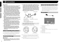
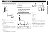
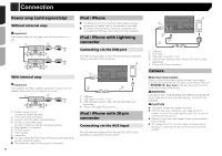
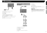
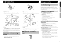
Connection 4 7 56 23 8 1 1 Rear view camera (ND-BC8) (sold separately) 2 To video output 3 RCA cable (supplied with ND-BC8) 4 This product 5 Brown (R.C IN) 6 Power supply 7 Power cord 8 Violet/white (REVERSE-GEAR SIGNAL INPUT) Power cord on page 33 Connect only the rear view camera to R.C IN. Do not connect any other equipment. Some appropriate settings are required to use other view cameras. Setting the rear view camera on page 23 External video component and the display 1 3 2 4 5 6 7 89 a b 3 9 Red, white a To Yellow b To Red, white c To video output d To audio outputs e External video component (sold separately) The appropriate setting is required to use the external video component. AUX source on page 23 WARNING NEVER install the rear display in a location that enables the driver to watch the video source while driving. This product's rear video output is for connection of a display to enable passengers in the rear seats to watch the video source. c d e 1 Rear display with RCA input jacks 2 To video input 3 RCA cables (sold separately) 4 This product 5 Yellow (V OUT) 6 AUX input 7 Mini-jack AV cable (CD-RM10) (sold separately) 8 Yellow 35
-
 1
1 -
2
-
3
-
4
-
5
-
6
-
7
-
8
-
9
-
10
-
11
-
12
-
13
-
14
-
15
-
16
-
17
-
18
-
19
-
20
-
21
-
22
-
23
-
24
-
25
-
26
-
27
-
28
-
29
-
 30
30 -
 31
31 -
 32
32 -
 33
33 -
 34
34 -
 35
35 -
 36
36 -
 37
37 -
 38
38 -
 39
39 -
 40
40 -
41
-
42
-
43
-
44
-
45
-
46
-
47
-
48
-
49
-
50
-
51
-
52
-
53
-
54
-
55
-
56
-
57
-
58
-
59
-
60
-
61
-
62
-
63
-
64
-
65
-
66
-
67
-
68
-
69
-
70
-
71
-
72
-
73
-
74
-
75
-
76
-
77
-
78
-
79
-
80
-
81
-
82
-
83
-
84
-
85
-
86
-
87
-
88
-
89
-
90
-
91
-
92
-
93
-
94
-
95
-
96
-
97
-
98
-
99
-
100
-
101
-
102
-
103
-
104
-
105
-
106
-
107
-
108
-
109
-
110
-
111
-
112
-
113
-
114
-
115
-
116
-
117
-
118
-
119
-
120
-
121
-
122
-
123
-
124
-
125
-
126
-
127
-
128
-
129
-
130
-
131
-
132
-
133
-
134
-
135
-
136
-
137
-
138
-
139
-
140
-
141
-
142
-
143
-
144
-
145
-
146
-
147
-
148
 |
 |
