Pioneer DEH 2000MP Owner's Manual - Page 15
DIN front/rear mount, Installation - parts
 |
UPC - 012562876603
View all Pioneer DEH 2000MP manuals
Add to My Manuals
Save this manual to your list of manuals |
Page 15 highlights
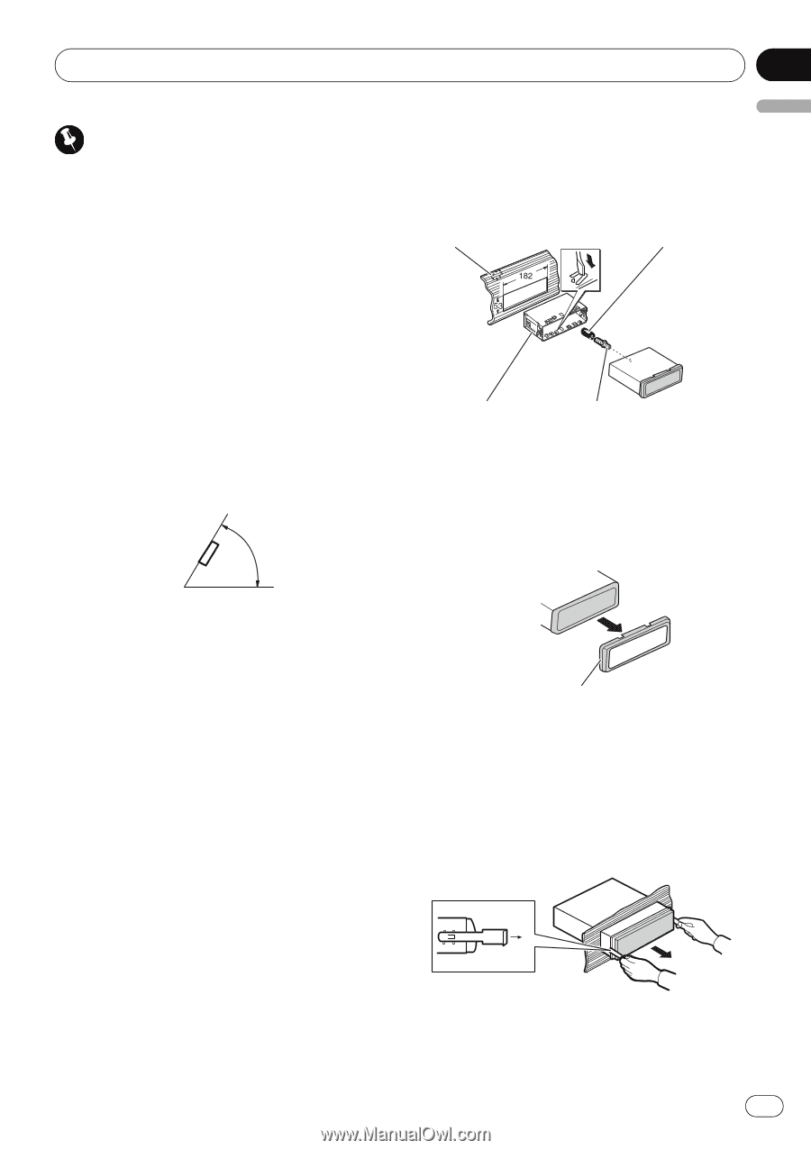
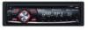
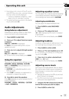
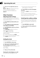
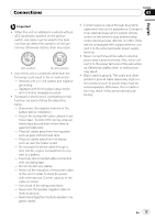
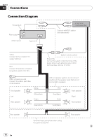
Installation Section 04 English Important ! Check all connections and systems before final installation. ! Do not use unauthorized parts. Use of unauthorized parts may cause malfunctions. ! Consult your dealer if installation requires drilling of holes or other modifications to the vehicle. ! Do not install this unit where : - it may interfere with operation of the vehicle. - it may cause injury to a passenger as a result of a sudden stop. ! The semiconductor laser will be damaged if it overheats. Install this unit away from hot places such as near the heater outlet. ! Optimum performance is obtained when the unit is installed at an angle of less than 60°. 60° 2 Secure the mounting sleeve by using a screwdriver to bend the metal tabs (90°) into place. 3 Install the unit. Dashboard Rubber bush Mounting sleeve Screw Removing the unit 1 Extend top and bottom of the trim ring outwards to remove the trim ring. (When reattaching the trim ring, point the side with a groove downwards and attach it.) DIN front/rear mount This unit can be properly installed either from "Front" (conventional DIN front-mount) or "Rear" (DIN rear-mount installation, utilizing threaded screw holes at the sides of unit chassis). For details, refer to the following installation methods. DIN Front-mount Installation with the rubber bush 1 Insert the mounting sleeve into the dashboard. When installing in a shallow space, use a supplied mounting sleeve. If there is enough space behind the unit, use factory supplied mounting sleeve. Trim ring ! It becomes easy to remove the trim ring if the front panel is released. 2 Insert the supplied extraction keys into both sides of the unit until they click into place. 3 Pull the unit out of the dashboard. En 15
-
 1
1 -
2
-
3
-
4
-
5
-
6
-
7
-
8
-
9
-
 10
10 -
 11
11 -
 12
12 -
 13
13 -
 14
14 -
 15
15 -
 16
16 -
 17
17 -
 18
18 -
 19
19 -
 20
20 -
21
-
22
-
23
-
24
-
25
-
26
-
27
-
28
-
29
-
30
-
31
-
32
-
33
-
34
-
35
-
36
-
37
-
38
-
39
-
40
-
41
-
42
-
43
-
44
-
45
-
46
-
47
-
48
-
49
-
50
-
51
-
52
-
53
-
54
-
55
-
56
-
57
-
58
-
59
-
60
-
61
-
62
 |
 |