Pioneer DEH-P300 Service Manual - Page 52
Adjustment - wiring
 |
View all Pioneer DEH-P300 manuals
Add to My Manuals
Save this manual to your list of manuals |
Page 52 highlights
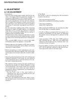
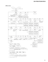
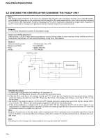
DEH-P300,P3000,P200 6. ADJUSTMENT 6.1 CD ADJUSTMENT 1) Precautions • This unit uses a single power supply (+5V) for the reg- ulator. The signal reference potential, therefore, is connected to REFO(approx. 2.5V) instead of GND. If REFO and GND are connected to each other by mistake during adjustments, not only will it be impossible to measure the potential correctly, but the servo will malfunction and a severe shock will be applied to the pick-up. To avoid this, take special note of the following. Do not connect the negative probe of the measuring equipment to REFO and GND together. It is especially important not to connect the channel 1 negative probe of the oscilloscope to REFO with the channel 2 negative probe connected to GND. Since the frame of the measuring instrument is usually at the same potential as the negative probe, change the frame of the measuring instrument to floating status. If by accident REFO comes in contact with GND, immediately switch the regulator or power OFF. • Always make sure the regulator is OFF when connecting and disconnecting the various filters and wiring required for measurements. • Before proceeding to further adjustments and measurements after switching regulator ON, let the player run for about one minute to allow the circuits to stabilize. • Since the protective systems in the unit's software are rendered inoperative in test mode, be very careful to avoid mechanical and /or electrical shocks to the system when making adjustment. • Disc detection during loading and eject operations is performed by means of a photo transistor in this unit.Consequently, if the inside of the unit is exposed to a strong light source when the outer casing is removed for repairs or adjustment, the following malfunctions may occur. *During PLAY, even if the eject button is pressed,the disc will not be ejected and the unit will remain in the PLAY mode. *The unit will not load a disc. When the unit malfunctions this way, either re-position the light source, move the unit or cover the photo transistor. 2) Test Mode This mode is used for adjusting the CD mechanism module of the device. • Test mode starting procedure Reset while pressing the 4 and 6 keys together. • Test mode cancellation Switch ACC, back-up OFF. • After pressing the EJECT key, do not press any other key until the disk is completely ejected. • If the ] or [ key is pressed while focus search is in progress, immediately turn the power off (otherwise the actuator may be damaged due to adhesion of the lenses). • Jump operation of TRs other than 100TR continues after releasing the key. CRG move and 100TR jump operations are brought into the "Tracking close" status when the key is released. • Powering Off/On resets the jump mode to "Single TR (91)", the RF AMP gain setting to 0 dB, and the automatic adjustment value to the initial value. 52
-
 1
1 -
2
-
3
-
4
-
5
-
6
-
7
-
8
-
9
-
10
-
11
-
12
-
13
-
14
-
15
-
16
-
17
-
18
-
19
-
20
-
21
-
22
-
23
-
24
-
25
-
26
-
27
-
28
-
29
-
30
-
31
-
32
-
33
-
34
-
35
-
36
-
37
-
38
-
39
-
40
-
41
-
42
-
43
-
44
-
45
-
46
-
 47
47 -
 48
48 -
 49
49 -
 50
50 -
 51
51 -
 52
52 -
 53
53 -
 54
54 -
 55
55 -
 56
56 -
 57
57 -
58
-
59
-
60
-
61
-
62
-
63
-
64
-
65
-
66
-
67
-
68
-
69
-
70
-
71
-
72
-
73
-
74
-
75
-
76
-
77
-
78
-
79
-
80
-
81
-
82
-
83
 |
 |