Pioneer DEH-P300 Service Manual - Page 82
See the DFS Alarm - installation manual
 |
View all Pioneer DEH-P300 manuals
Add to My Manuals
Save this manual to your list of manuals |
Page 82 highlights
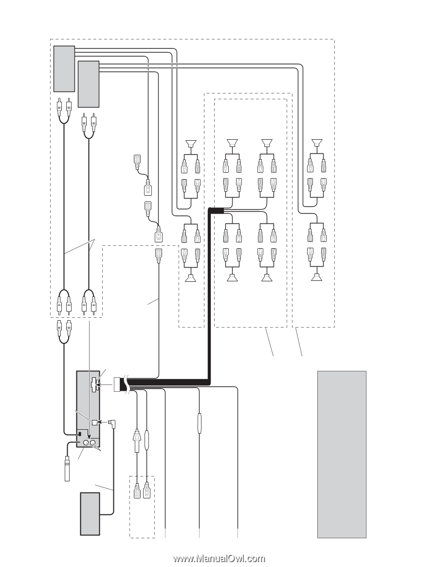
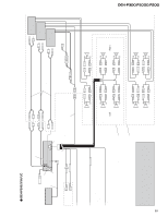
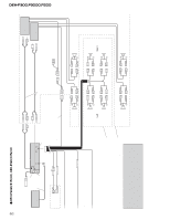
DEH-P300,P3000,P200 82 - DEH-P3000/X1N/UC, DEH-P200/X1N/UC Antenna jack This Product Multi-CD player (sold separately) IP-BUS cable Rear output IP-BUS input (Blue) See the section "DFS Alarm Installation". Brown White/yellow Fuse holder Fuse resistor Front output Fuse Blue/white To system control terminal of the power amp or Auto-antenna relay control terminal. (Max. 300 mA 12 V DC.) Yellow To terminal always supplied with power regardless of ignition switch position. Red To electric terminal controlled by ignition switch (12 V DC) ON/OFF. Black (ground) To vehicle (metal) body. Fuse resistor With a 2 speaker system, do not connect anything to the speaker leads that are not connected to speakers. + Front speaker ≠ + Front speaker ≠ Left + Rear speaker ≠ Perform these connections when using a different amp (sold separately). Note: The electrical leads of this product may be different colors to the corresponding leads (i.e. the leads that serve the same function) of other products. When connecting this product to another product, please read the instruction manual for each product carefully and then connect each lead of this product to the other product that serves the same function. + Rear speaker ≠ Connecting cords with RCA pin plugs (sold separately) System remote control White White/black Green Green/black Gray Gray/black Violet Violet/black Power amp (sold separately) Power amp (sold separately) + Front speaker ≠ + Front speaker ≠ Right + Rear speaker ≠ + Rear speaker ≠
-
 1
1 -
2
-
3
-
4
-
5
-
6
-
7
-
8
-
9
-
10
-
11
-
12
-
13
-
14
-
15
-
16
-
17
-
18
-
19
-
20
-
21
-
22
-
23
-
24
-
25
-
26
-
27
-
28
-
29
-
30
-
31
-
32
-
33
-
34
-
35
-
36
-
37
-
38
-
39
-
40
-
41
-
42
-
43
-
44
-
45
-
46
-
47
-
48
-
49
-
50
-
51
-
52
-
53
-
54
-
55
-
56
-
57
-
58
-
59
-
60
-
61
-
62
-
63
-
64
-
65
-
66
-
67
-
68
-
69
-
70
-
71
-
72
-
73
-
74
-
75
-
76
-
 77
77 -
 78
78 -
 79
79 -
 80
80 -
 81
81 -
 82
82 -
 83
83
 |
 |