Pioneer DEH-P300 Service Manual - Page 61
Pioneer DEH-P300 Manual
 |
View all Pioneer DEH-P300 manuals
Add to My Manuals
Save this manual to your list of manuals |
Page 61 highlights
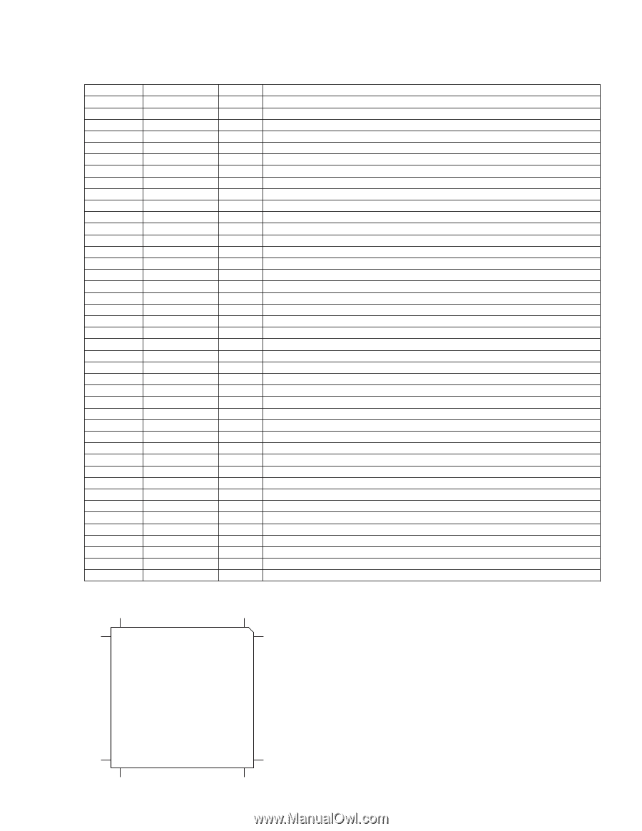
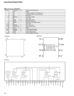
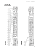
DEH-P300,P3000,P200 Pin No. 59 60 61 62 63 64 65 66 67 68 69 70 71 72 73 74 75 76 77 78 79 80 81 82 83 84 85 86 87 88 89 90 91 92 93 94 95 96 97 98 99 100 Pin Name ATEST RFMODE A.GND FD TD SD MD DACO FBAL TBAL TEVCA A.VDD EFM ASY C3T RFI AGCO AGCI RFO EQ2 EQ1 RFA.GND A C B D F E A.VDD REFOUT FEFEO TETEO TE2 TEC A.GND PD LD PN A.VDD *UPD63710GC 250 216 I/O Function and Operation I/O Test pin I Use/not use select for internal RF amplifier Analog circuit GND O Focus drive output O Tracking drive output O Sled drive output O Spindle drive output O DAC output for adjustment O DAC output for adjustment O DAC output for adjustment O DAC output for adjustment Power supply terminal to analog circuit O EFM signal output I EFM comparator reference voltage input 3T detection capacitor additional pin I RF signal input for EFM data regulation O RF signal output of after gain adjustment I RF-AGC amplifier input O RF summing amplifier output RF amplifier equalizer parts additional pin RF amplifier equalizer parts additional pin I RF summing amplifier inverted input Analog circuit GND I Photo detector A input I Photo detector C input I Photo detector B input I Photo detector D input I Photo detector F input I Photo detector E input Positive power supply terminal to analog circuit O Reference electric potential output I Focus error amplifier inverted input I/O Focus error amplifier output I Tracking error amplifier inverted input I/O Tracking error amplifier output I/O Tracking error output of after amplification I Tracking comparator input Analog circuit GND I PD detection signal input for LD output monitor O LD control current output I APC circuit control polarity set pin Positive power supply terminal to analog circuit 1 1800 451 450 7661 6705 61
-
 1
1 -
2
-
3
-
4
-
5
-
6
-
7
-
8
-
9
-
10
-
11
-
12
-
13
-
14
-
15
-
16
-
17
-
18
-
19
-
20
-
21
-
22
-
23
-
24
-
25
-
26
-
27
-
28
-
29
-
30
-
31
-
32
-
33
-
34
-
35
-
36
-
37
-
38
-
39
-
40
-
41
-
42
-
43
-
44
-
45
-
46
-
47
-
48
-
49
-
50
-
51
-
52
-
53
-
54
-
55
-
 56
56 -
 57
57 -
 58
58 -
 59
59 -
 60
60 -
 61
61 -
 62
62 -
 63
63 -
 64
64 -
 65
65 -
 66
66 -
67
-
68
-
69
-
70
-
71
-
72
-
73
-
74
-
75
-
76
-
77
-
78
-
79
-
80
-
81
-
82
-
83
 |
 |