Pioneer DJM 600 Owner's Manual - Page 6
Connections - back
 |
UPC - 012562506258
View all Pioneer DJM 600 manuals
Add to My Manuals
Save this manual to your list of manuals |
Page 6 highlights
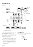
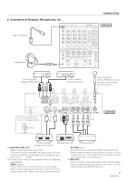
CONNECTIONS When connecting or changing the connection of units, make sure to first turn off the power switch and disconnect the power cord from the outlet. 1. Connection of Input Equipment DAT, etc. CD 2 CDJ-100S/ CDJ-700S/ CDJ-500 II CD 1 CDJ-100S/ CDJ-700S/ CDJ-500 II DAT, etc. *1 RL RL RL RL Control cord *2 (Can be connected to the CDJ-100S, CDJ-700S and CDJ-500 II, etc.) MASTER BOOTH OUT 1 MONITOR L CH - 4 PHONO 3 LINE L CH - 3 PHONO 2 LINE L CH - 2 PHONO 1 CD 2 /LINE CH - 1 LINE CD 1 /LINE L L R R MASTER LEVEL ATT. R R R SIGNAL GND CH - 2 CH - 1 PLAYER CONTROL 220-230 110-120V -240V VOLTAGE SELECTOR MASTER R OUT2 R 2 COLD 3 HOT L R L R L L 1 GND REC OUT R L R L R LR L SEND (MONO) RETURN (MONO) CH - 4 SUBMIC DJM-600 Connect to a wall's electrical outlet Player 3 *3 (PHONO 3 cannot be used if connecting a sub-microphone.) Player 2 *3 If connecting an analog player, remove the six short-circuit pin plugs inserted in the PHONO terminals (PHONO 1, PHONO 2 and PHONO 3) of CH-2, CH-3, and CH-4. These short-circuit pin plugs serve to cut fine noise, ensuring outstanding performance when no analog player is connected. Make sure to store the plugs carefully after removing them. When you disconnect an analog player, reinsert the plugs as they were originally. *1 Connect the cord for the analog player's ground. This terminal is exclusively for an analog player and is not a safety earth. *2 If you are using the unit with the separately sold CDJ100S, CDJ-700S, or CDJ-500 II connected to the CH-1 or CH-2 CD terminals, the fader start function can be used if the unit and CD player are connected with a control cord. *3 Because the unit's PHONO input terminals are exclusively for MM, use MM-type cartridges for the analog player connected. 6 Player 1 *3 Cassette deck, etc. Connecting audio cords Use the cords with the red and white pin plugs. Connect the white plug to "L" and the red plug to "R". Make sure to insert the plugs completely. White plug L Red plug R
-
 1
1 -
 2
2 -
 3
3 -
 4
4 -
 5
5 -
 6
6 -
 7
7 -
 8
8 -
 9
9 -
 10
10 -
 11
11 -
 12
12 -
13
-
14
-
15
-
16
-
17
-
18
-
19
-
20
-
21
-
22
-
23
-
24
-
25
-
26
-
27
-
28
 |
 |
