Pioneer DJM-700 Owner's Manual - Page 9
Names And Functions Of Parts
 |
UPC - 012562860862
View all Pioneer DJM-700 manuals
Add to My Manuals
Save this manual to your list of manuals |
Page 9 highlights
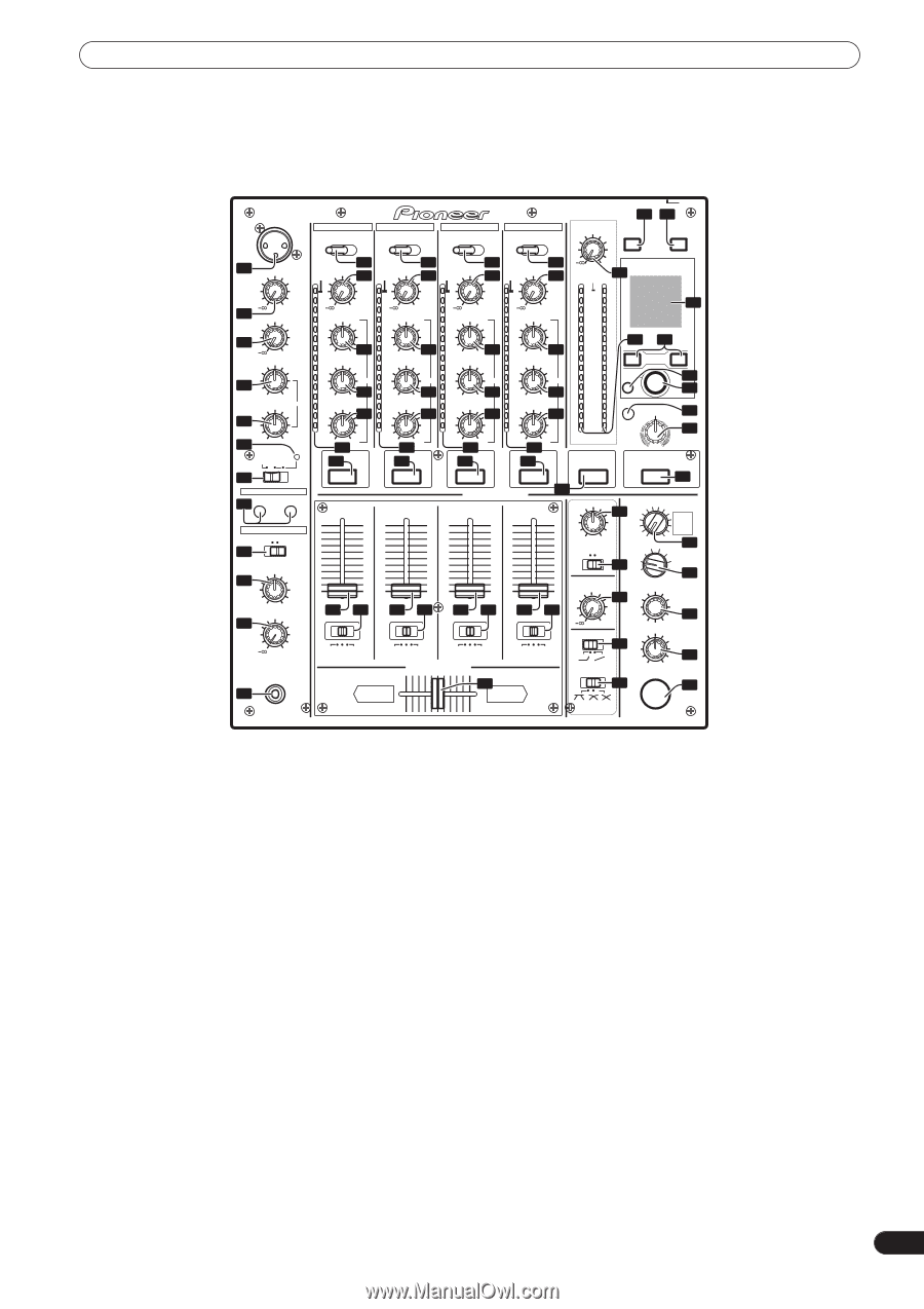
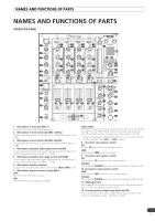
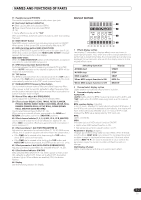
NAMES AND FUNCTIONS OF PARTS NAMES AND FUNCTIONS OF PARTS OPERATION PANEL MIC1 CH-1 CD LINE CH-2 CD PHONO CH-3 LINE PHONO PROFESSIONAL MIXIER CH-4 MASTER LEVEL LINE PHONO POWER DJM3-7 3 0034 MIDI ON/OFF START/STOP 1 MIC1 LEVEL 8 9 10 10 11 11 11 11 OVER TRIM OVER TRIM OVER TRIM OVER TRIM 0 23 OVER BEAT EFFECTS 2 0 MIC2 LEVEL 3 0 HI 4 -12 +12 LOW EQ 5 6 -12 +12 MIC TALK OFF ON OVER 7 FADER START 17 CH-1 CH-2 HEADPHONES MONO SPLIT STEREO 28 MIXING 29 30 CUE MASTER LEVEL 0 PHONES 31 10 10 10 10 10 7 +9 7 +9 7 +9 7 +9 7 4 HI 4 HI 4 HI 4 HI 4 44 2 1 0 -26 +612 -1 MID -2 -3 -5 -7 -26 EQ +613 -10 LOW -15 14 2 1 0 -26 +6 12 -1 MID -2 -3 -5 -7 -26 EQ +6 13 -10 LOW -15 14 2 1 0 -26 +6 12 -1 MID -2 -3 -5 -7 -26 EQ +6 13 -10 LOW -15 14 2 1 0 -26 +6 12 -1 MID -2 -3 -5 -7 -26 EQ +6 13 -10 LOW -15 14 2 1 24 32 0 -1 2 BEAT 3 -2 -3 AUTO 35 -5 TAP 36 -7 -10 FILTER 37 FREQUENCY -15 -24 dB 15 -26 +6 16 1 -24 dB 15 -26 +6 16 2 -24 dB 15 -26 +6 16 3 -24 dB 15 -26 +6 16 4 -24 L dB R MASTER 38 LPF HPF EFFECTS 16 HEADPHONES CUE 16 10 9 8 7 6 5 4 3 2 1 0 18 19 10 9 8 7 6 5 4 3 2 1 0 18 10 9 8 7 6 5 4 3 2 1 0 19 18 10 9 8 7 6 5 4 3 2 1 0 19 18 19 A THRU B A THRU B A THRU B A THRU B CROSS FADER ASSIGN 22 A B BALANCE REVERB 25 PHASER FLANGER FILTER TRANS ECHO ROBOT CRUSH ROLL ROLL REVERSE UP DOWN L R MONO STEREO 26 DELAY 4 3 2 1 39 SND/RTN MIC CF.A CF.B 40 MASTER BOOTH MONITOR LEVEL 27 TIME 0 CH FADER 20 CROSS FADER 21 41 LEVEL/DEPTH MIN MAX ON/OFF 42 43 1 Microphone 1 input jack (MIC 1) Connect microphone with XLR-type plug. 2 Microphone 1 level control dial (MIC 1 LEVEL) Use to adjust the volume of microphone 1. (adjustable range -∞ to 0 dB) 3 Microphone 2 level control dial (MIC 2 LEVEL) Use to adjust the volume of microphone 2. (adjustable range -∞ to 0 dB) 4 Microphone equalizer high-range control dial (HI) Use to adjust the treble (high-range) frequencies of microphones 1 and 2. (adjustable range -12 dB to +12 dB) 5 Microphone equalizer low-range control dial (LOW) Use to adjust the bass (low-range) frequencies of microphones 1 and 2. (adjustable range -12 dB to +12 dB) 6 Microphone function indicator Lights when microphone is ON; flashes when TALK OVER is ON. 7 Microphone function selector switch (MIC) OFF: No microphone sound is output. ON: Microphone sound is output normally. TALK OVER: Microphone sound is output; when sound is input to a connected microphone, the TALK OVER function operates and all sound other than that from the microphone is attenuated by 20 dB. • When not using the TALK OVER function, it is recommended to set the switch to the [OFF] or [ON] position. 8 Channel 1 input selector switch CD: Selects CD input (line level analog input). LINE: Use to select LINE input connectors. 9 Channel 2 input selector switch CD: Use to select CD input (line level analog input). PHONO: Use to select PHONO input connectors (analog turntable input). 10 Channel 3, 4 input selector switch LINE: Use to select LINE input (line level analog input). PHONO: Use to select PHONO input connectors (analog turntable input). 11 TRIM adjust dial Use to adjust the input level for each channel. (adjustable range: - ∞ to +9 dB, mid-position is about 0 dB) 12 Channel equalizer high-range adjust dial (HI) Use to adjust the treble (high-range) frequency sound for each channel. (adjustable range: -26 dB to +6 dB) 9 En
-
 1
1 -
2
-
3
-
 4
4 -
 5
5 -
 6
6 -
 7
7 -
 8
8 -
 9
9 -
 10
10 -
 11
11 -
 12
12 -
 13
13 -
 14
14 -
15
-
16
-
17
-
18
-
19
-
20
-
21
-
22
-
23
-
24
-
25
-
26
-
27
-
28
 |
 |