Pioneer GM-6500F Owner's Manual - Page 10
Connecting the speaker, output terminals, Connecting the units
 |
View all Pioneer GM-6500F manuals
Add to My Manuals
Save this manual to your list of manuals |
Page 10 highlights
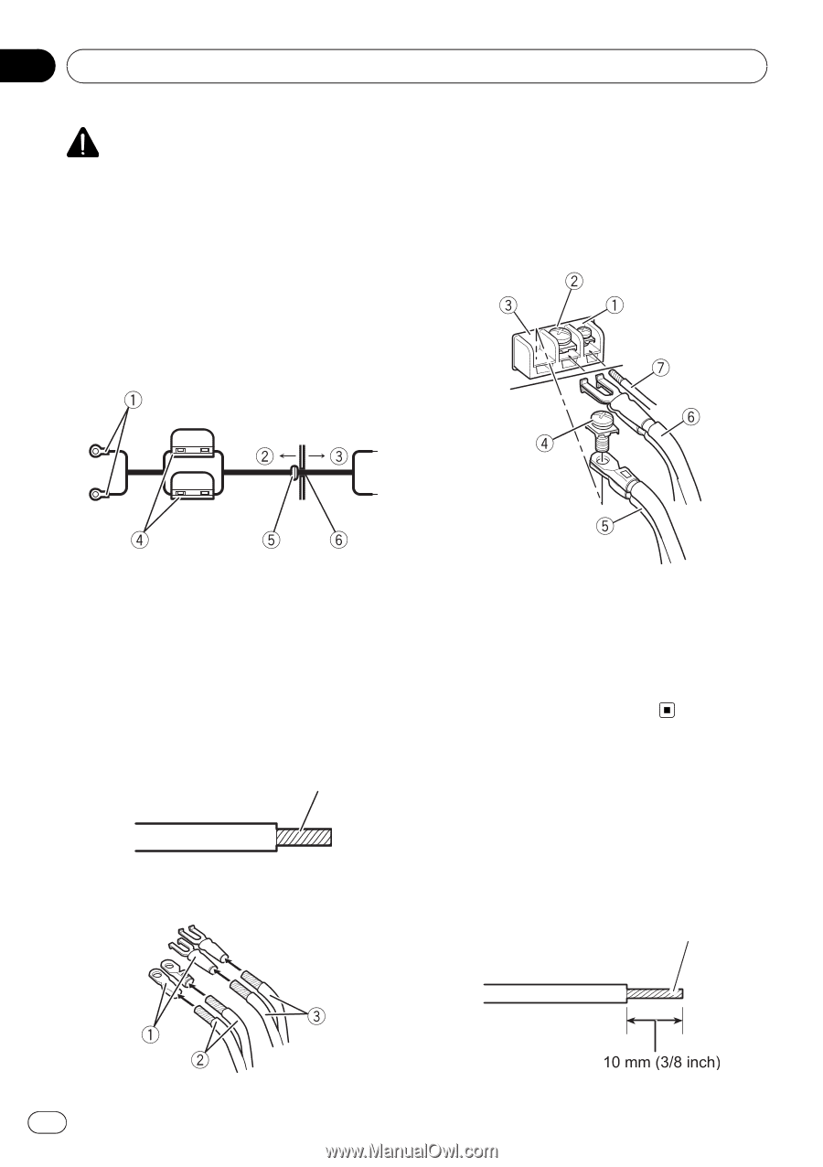
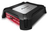
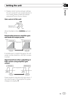
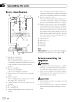
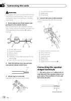
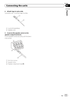
Section 03 Connecting the units WARNING If the battery wire is not securely fixed to the terminal using the terminal screws, there is a risk of overheating, malfunction and injury, including minor burns. 1 Route battery wire from engine compartment to the vehicle interior. After completing all other amplifier connections, finally connect the battery wire terminal of the amplifier to the positive (+) battery terminal. 1 Lug (sold separately) 2 Battery wire 3 Ground wire 4 Connect the wires to the terminal. Fix the wires securely with the terminal screws. 1 Positive (+) terminal 2 Engine compartment 3 Vehicle interior 4 Fuse (30 A) × 2 5 Insert the O-ring rubber grommet into the vehicle body. 6 Drill a 14 mm hole into the vehicle body. 2 Twist the battery wire, ground wire and system remote control wire. Twist 3 Attach lugs to wire ends. Use pliers, etc., to crimp lugs to wires. 1 System remote control terminal 2 Ground terminal 3 Power terminal 4 Terminal screws 5 Battery wire 6 Ground wire 7 System remote control wire Connecting the speaker output terminals 1 Use wire cutters or a utility knife to strip the end of the speaker wires to expose about 10 mm (3/8 in.) of wire and then twist the wire. Twist 10 En
-
 1
1 -
2
-
3
-
4
-
 5
5 -
 6
6 -
 7
7 -
 8
8 -
 9
9 -
 10
10 -
 11
11 -
 12
12 -
 13
13 -
 14
14 -
 15
15 -
16
-
17
-
18
-
19
-
20
-
21
-
22
-
23
-
24
-
25
-
26
-
27
-
28
-
29
-
30
-
31
-
32
-
33
-
34
-
35
-
36
-
37
-
38
-
39
-
40
 |
 |