Pioneer GM-6500F Owner's Manual - Page 6
Connection diagram, Before connecting the, amplifier, Connecting the units - wiring
 |
View all Pioneer GM-6500F manuals
Add to My Manuals
Save this manual to your list of manuals |
Page 6 highlights
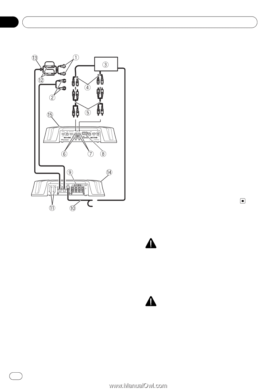
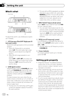
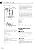
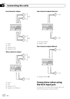
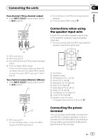
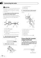
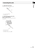
Section 03 Connecting the units Connection diagram Please see the following section for speaker connection instructions. Refer to Connections when using the speaker input wire on page 9. 9 Speaker output terminals Please see the following section for speaker connection instructions. Refer to Connections when using the speaker input wire on page 9. a System remote control wire (sold separately) Connect male terminal of this wire to the system remote control terminal of the car stereo. The female terminal can be connected to the auto-antenna relay control terminal. If the car stereo lacks a system remote control terminal, connect the male terminal to the power terminal via the ignition switch. b Fuse (25 A) × 2 c Fuse (30 A) × 2 d Grommet e Rear side f Front side Note INPUT SELECT (input select) switch must be set. For details, see Setting the unit on page 4. 1 Special red battery wire RD-223 (sold separately) After completing all other amplifier connections, finally connect the battery wire terminal of the amplifier to the positive (+) battery terminal. 2 Ground wire (Black) RD-223 (sold separately) Connect to metal body or chassis. 3 Car stereo with RCA output jacks (sold separately) 4 External output If only one input plug is used, do not connect anything to RCA input jack B. 5 Connecting wire with RCA pin plugs (sold separately) 6 RCA input jack A 7 RCA input jack B 8 Speaker input terminal (use a connector in- cluded) Before connecting the amplifier WARNING ! Secure the wiring with cable clamps or adhe- sive tape. To protect the wiring, wrap sections in contact with metal parts in adhesive tape. ! Never cut the insulation of the power supply to feed power to other equipment. Current capacity of the wire is limited. CAUTION ! Never shorten any wires, the protection circuit may malfunction. ! Never ground speaker wire directly or band to- gether multiple speakers' negative (*) lead wires. 6 En
-
 1
1 -
 2
2 -
 3
3 -
 4
4 -
 5
5 -
 6
6 -
 7
7 -
 8
8 -
 9
9 -
 10
10 -
 11
11 -
 12
12 -
13
-
14
-
15
-
16
-
17
-
18
-
19
-
20
-
21
-
22
-
23
-
24
-
25
-
26
-
27
-
28
-
29
-
30
-
31
-
32
-
33
-
34
-
35
-
36
-
37
-
38
-
39
-
40
 |
 |