Pioneer GM-D9500F Owner's Manual - Page 13
Before installing the amplifier, Example of installation on, the floor mat or chassis, Installation
 |
UPC - 012562967608
View all Pioneer GM-D9500F manuals
Add to My Manuals
Save this manual to your list of manuals |
Page 13 highlights
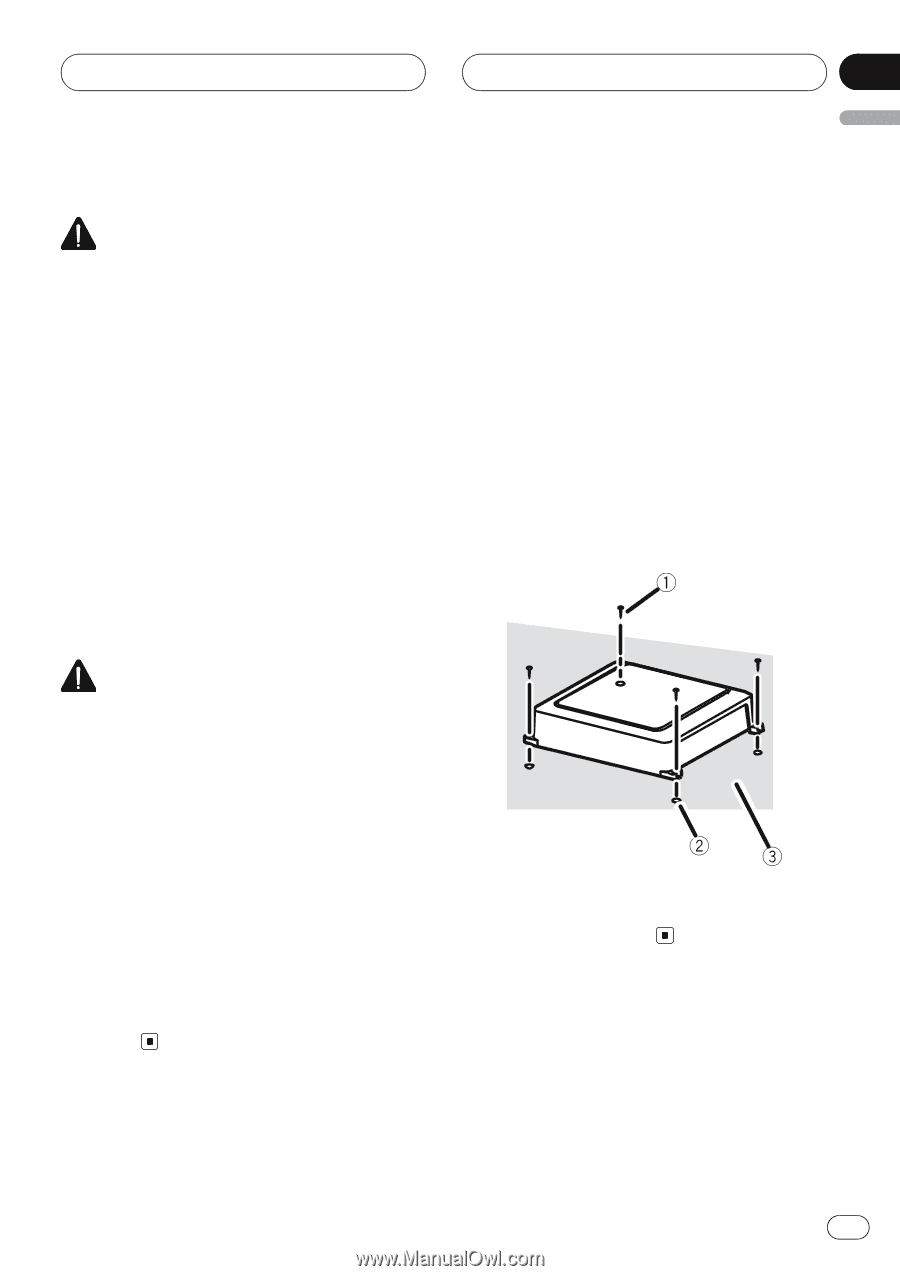
Installation Section 04 English Before installing the amplifier WARNING ! Do not use unauthorized parts as this may cause malfunctions. ! Do not install this unit where : - it may interfere with operation of the vehicle. - it may cause injury to a passenger as a result of a sudden stop. ! Install tapping screws in such a way that the screw tip does not touch any wire. This is important to prevent wires from being cut by vibration of the car, which can result in fire. ! Place all cables away from moving parts, such as the gear shift and seat rails. ! When drilling to install the amplifier, always confirm no parts are behind the panel and protect all cables and important equipment (e.g. fuel/brake lines, wiring) from damage. Example of installation on the floor mat or chassis 1 Place the amplifier in the desired installation location. Insert the supplied tapping screws (4 mm × 18 mm) into the screw holes and push on the screws with a screwdriver so they make an imprint where the installation holes are to be located. 2 Drill 2.5 mm (1/8 in.) diameter holes at the imprints either on the carpet or directly on the chassis. 3 Install the amplifier with the use of supplied tapping screws (4 mm × 18 mm). CAUTION ! To ensure proper heat dissipation of the ampli- fier, ensure the following during installation: - Allow adequate space above the amplifier for proper ventilation. - Do not cover the amplifier with a floor mat or carpet. ! Place all cables away from hot places, such as near the heater outlet. ! The optimal installation location differs de- pending on the car model. Secure the amplifier at a sufficiently rigid location. ! Check all connections and systems before final installation. ! After installing the amplifier, confirm that the spare tire, jack and tools can be easily removed. 1 Tapping-screws (4 mm × 18 mm) 2 Drill a 2.5 mm (1/8 in.) diameter hole 3 Floor mat or chassis En 13
-
 1
1 -
2
-
3
-
4
-
5
-
6
-
7
-
 8
8 -
 9
9 -
 10
10 -
 11
11 -
 12
12 -
 13
13 -
 14
14 -
 15
15 -
 16
16 -
 17
17 -
 18
18 -
19
-
20
-
21
-
22
-
23
-
24
-
25
-
26
-
27
-
28
-
29
-
30
-
31
-
32
-
33
-
34
-
35
-
36
-
37
-
38
-
39
-
40
-
41
-
42
-
43
-
44
 |
 |