Pioneer PDP-427CMX User Manual - Page 18
Installation and Connections - wall mount
 |
View all Pioneer PDP-427CMX manuals
Add to My Manuals
Save this manual to your list of manuals |
Page 18 highlights
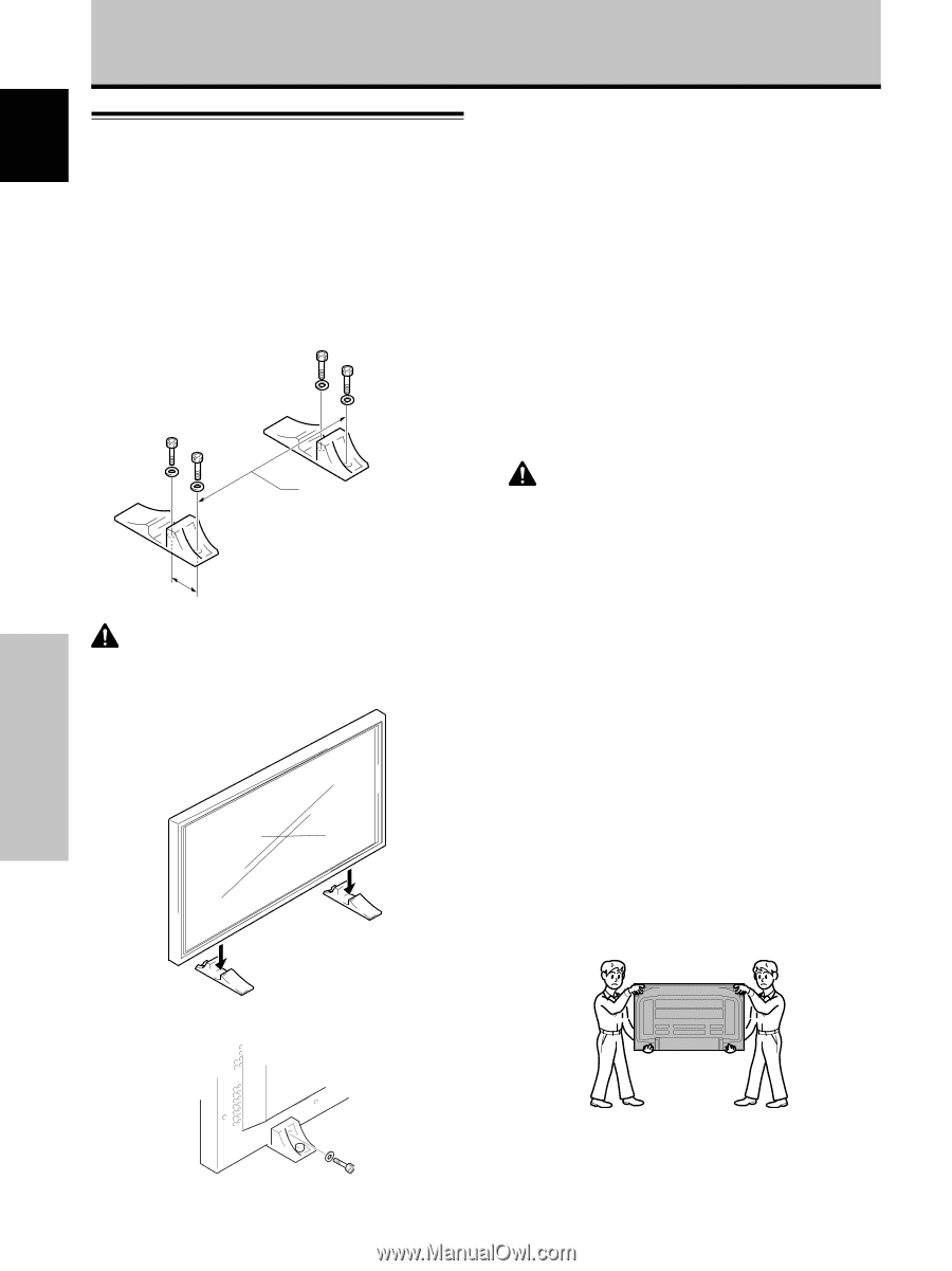
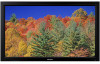
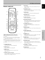
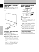
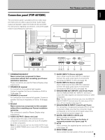
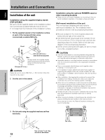
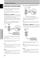
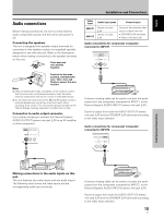
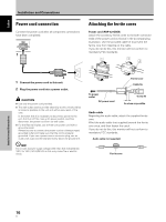
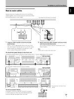
English Installation and Connections Installation of the unit Installation using the supplied display stands (PDP-427CMX) Be sure to fix the supplied stands to the installation surface. Use commercially available M8 bolts that are 25 mm (1 in.) longer than the thickness of the installation surface. 1 Fix the supplied stands to the installation surface at each of the 4 prepared holes using commercially available M8 bolts. Front Rear 517 mm (20-3/8 in.) (Bolt hole thread pitch) Always install the supplied display stands according to the dimensions shown in the accompanying illustration. 110 mm (4-5/16 in.) CAUTION Please be sure to use an M8 (Pitch = 1.25 mm) bolt. (Only this size bolt can be used.) 2 Set this unit in the stands. Installation using the optional PIONEER stand or other mounting brackets ÷ Please be sure to request installation or mounting of this unit by an installation specialist or the dealer where purchased. Wall-mount installation of the unit This unit has been designed with bolt holes for wall-mount installation, etc. The installation holes provided are shown in the accompanying illustration. ÷ Be sure to attach in 4 or more locations above and below, left and right of the center line. ÷ Use bolts that are long enough to be inserted 12 mm (1/2 in.) to 18 mm (11/16 in.) into the main unit from the attaching surface for a holes. Refer to the side view diagram in the accompanying illustration. ÷ As this unit is constructed with glass, be sure to install it on a flat, unwarped surface. CAUTION ÷ Use only those stands or mounting brackets designated by Pioneer. If other non-recommended products are used, the unit may fall and be damaged or otherwise malfunction. ÷ Assemble stands or mounting brackets correctly in accordance with the instructions provided or other applicable installation instructions. ÷ Two or more people should always work together when installing or removing this unit. ÷ The installation location selected should be fully capable of supporting the weight of this unit, and be a stable, flat, and even surface. If installed in other locations, the unit may fall or be damage. ÷ After installation, take appropriate measures to prevent the installation from falling. The failure to take such measures could allow the unit to fall, causing injuries or damage. ÷ When this unit is installed on a wall, the work should be done by a professional technician possessing the requisite technical knowledge and abilities; consult your dealer for more information. Improper or insufficient installation may result in accidents, damage or personal injury. ÷ Handles should not be removed or reattached by anyone other than the professional installation technician or service personnel. ÷ When moving the display, it should always be carried by two persons holding the rear handles in the manner shown. Never attempt to move the Plasma Display by holding only one of the handles. 3 Fix this unit using the supplied washers and hex hole bolts. Installation and Connections Use a 6 mm (1/4 in.) hex wrench to bolt them. 12 En
-
 1
1 -
2
-
3
-
4
-
5
-
6
-
7
-
8
-
9
-
10
-
11
-
12
-
 13
13 -
 14
14 -
 15
15 -
 16
16 -
 17
17 -
 18
18 -
 19
19 -
 20
20 -
 21
21 -
 22
22 -
 23
23 -
24
-
25
-
26
-
27
-
28
-
29
-
30
-
31
-
32
-
33
-
34
-
35
-
36
-
37
-
38
-
39
-
40
-
41
-
42
-
43
-
44
-
45
-
46
-
47
-
48
-
49
-
50
-
51
-
52
-
53
-
54
-
55
-
56
-
57
-
58
-
59
-
60
-
61
-
62
-
63
-
64
-
65
-
66
-
67
-
68
-
69
-
70
-
71
-
72
-
73
-
74
-
75
-
76
-
77
-
78
-
79
-
80
-
81
-
82
-
83
-
84
-
85
-
86
-
87
-
88
-
89
-
90
-
91
-
92
-
93
-
94
-
95
-
96
-
97
-
98
-
99
-
100
-
101
-
102
-
103
-
104
-
105
-
106
-
107
-
108
-
109
-
110
-
111
-
112
-
113
-
114
-
115
-
116
-
117
-
118
-
119
-
120
-
121
-
122
-
123
-
124
-
125
-
126
-
127
-
128
-
129
-
130
-
131
-
132
-
133
-
134
-
135
-
136
-
137
-
138
-
139
-
140
-
141
-
142
-
143
-
144
-
145
-
146
-
147
-
148
-
149
-
150
-
151
-
152
-
153
-
154
-
155
-
156
-
157
-
158
-
159
-
160
-
161
-
162
-
163
-
164
 |
 |