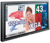
Pioneer PDP-433CMX Operating Instructions - Page 15
AUDIO OUTPUT Stereo mini jack - power
 |
View all Pioneer PDP-433CMX manuals
Add to My Manuals
Save this manual to your list of manuals |
Page 15 highlights
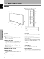
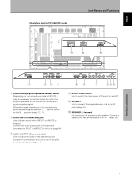
English Illustration depicts PDP-503CMX model. Part Names and Functions AC INLET - = 8Ω ~16Ω SPEAKER + - L ~ R 8Ω ~16Ω S+PEAKE-R CONTROL IN OUT COMBINATION IN OUT RS-232C INPUT1 (ON SYNC) ANALOG RGB OUTPUT (ANALOG RGB) G B INPUT2 (H/V SYNC) R HD VD 7Ω5Ô2k.Ω2 AUDIO INPUT OUTPUT (INPUT1/2) 1 23 4 56 7 89 0 8 Synchronizing signal impedance selector switch Depending on the connections made at INPUT2, it may be necessary to set this switch to match the output impedance of the connected component's synchronization signal. When the output impedance of the component's synchronization signal is below 75 Ω, set this switch to the 75 Ω position (pages 12, 14). 9 AUDIO INPUT (Stereo mini jack) Use to obtain sound when INPUT1 or INPUT2 is selected. Connect the audio output jack of components connected to INPUT1 or INPUT2 to this unit (page 14). 0 AUDIO OUTPUT (Stereo mini jack) Use to output the audio of the selected source component connected to this unit to an AV amplifier or similar component (page 14). - MAIN POWER switch Use to switch the main power of the unit on and off. = AC INLET Use to connect the supplied power cord to an AC outlet (page 15). ~ SPEAKER (L) terminal For connection of an external left speaker. Connect a speaker that has an impedance of 8 -16 Ω (page 14). Part Names and Functions 9 En
-
 1
1 -
2
-
3
-
4
-
5
-
6
-
7
-
8
-
9
-
 10
10 -
 11
11 -
 12
12 -
 13
13 -
 14
14 -
 15
15 -
 16
16 -
 17
17 -
 18
18 -
 19
19 -
 20
20 -
21
-
22
-
23
-
24
-
25
-
26
-
27
-
28
-
29
-
30
-
31
-
32
-
33
-
34
-
35
-
36
-
37
-
38
-
39
-
40
-
41
-
42
-
43
-
44
 |
 |
