Pioneer VSX-40 Owner's Manual - Page 19
Component Video Monitor Out, Component Video In 1, Component Video In 2, Dvr/bdr, Signal Sel
 |
View all Pioneer VSX-40 manuals
Add to My Manuals
Save this manual to your list of manuals |
Page 19 highlights
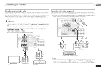
Connecting your equipment 02 Using the component video jacks Component video should deliver superior picture quality when compared to composite video. A further advantage (if your source and TV are both compatible) is progressive-scan video, which delivers a very stable, flicker-free picture. See the manuals that came with your TV and source component to check whether they are compatible with progressive-scan video. • For the audio connection, refer to Connecting your DVD player with no HDMI output on page 17. Important • If you connect any source component to the receiver using a component video input, you must also have your TV connected to this receiver's COMPONENT VIDEO MONITOR OUT jacks. • If necessary, assign the component video inputs to the input source you've connected. This only needs to be done if you didn't connect according to the following defaults: - COMPONENT VIDEO IN 1: DVD - COMPONENT VIDEO IN 2: DVR/BDR See The Input Assign menu on page 40 for more on this. VIDEO DVR/BDR CD-R/TAPE ZONE2 IR IN MONITOR TV/SAT BD OUT IN IN OUT L ADAPTER PORT (OUTPUT 5 V OUT 0.1 A MAX) R ANTENNA OUT 12 V TRIGGER (OUTPUT 12 V 50 mA MAX) DVR/ BDR OUT IN 1 (DVD) ASSIGN ABLE IN 2 (DVR/ BDR) IN DVD IN IN IN CD L FM UNBAL 75 IN SIRIUS AM LOOP A R FRONT R L IN L IN CENTER MONITOR OUT Y PB PR COMPONENT VIDEO TV/SAT BD R DVD SUBWOOFER PRE OUT Connecting other audio components The number and kind of connections depends on the kind of component you're connecting. Follow the steps below to connect a CD-R, MD, DAT, tape recorder or other audio component. • Note that you must connect digital components to analog audio jacks if you want to record to/from digital components (like an MD) to/from analog components. HDMI DVR/BDR IN DVD IN BD IN VIDEO 1 IN OUT COAXIAL IN 1 IN 1 ASSIGNABLE IN OPTICAL 2 ASSIGNABLE IR IN OUT 12 V TRIGGER (OUTPUT 12 V 50 mA MAX) VIDEO (CD) AUDIO DVR/BDR CD-R/TAPE ZONE2 (TV/SAT) (CD-R/TAPE) MONITOR TV/SAT BD OUT IN IN OUT L ADAPTER PORT (OUTPUT 5 V OUT 0.1 A MAX) R ANTENNA DVR/ BDR OUT IN 1 (DVD) ASSIGN ABLE IN 2 (DVR/ BDR) IN DVD IN IN IN CD L FM UNBAL 75 IN SIRIUS AM LOOP A R FRONT R L IN L IN CENTER MONITOR OUT Y PB PR COMPONENT VIDEO TV/SAT BD R DVD SUBWOOFER PRE OUT R REC L ANALOG AUDIO IN R L COAXIAL OPTICAL ANALOG AUDIO OUT DIGITAL AUDIO OUT Select one CD-R, MD, DAT, Tape recorder, etc. PR PB Y COMPONENT VIDEO OUT Note • In order to listen to the audio from the CD player that is connected to this receiver using a coaxial cable, first, switch to the CD-R input, then use RECEIVER and SIGNAL SEL to PR PB Y COMPONENT VIDEO IN choose the audio signal C1 (COAXIAL1) (see Selecting the audio input signal on page 26). TV DVD player 19 En
-
 1
1 -
2
-
3
-
4
-
5
-
6
-
7
-
8
-
9
-
10
-
11
-
12
-
13
-
 14
14 -
 15
15 -
 16
16 -
 17
17 -
 18
18 -
 19
19 -
 20
20 -
 21
21 -
 22
22 -
 23
23 -
 24
24 -
25
-
26
-
27
-
28
-
29
-
30
-
31
-
32
-
33
-
34
-
35
-
36
-
37
-
38
-
39
-
40
-
41
-
42
-
43
-
44
-
45
-
46
-
47
-
48
-
49
-
50
-
51
-
52
-
53
-
54
-
55
-
56
 |
 |
