Pioneer VSX-40 Owner's Manual - Page 22
Connect the IR receiver sensor to the IR IN jack on - mcacc manual
 |
View all Pioneer VSX-40 manuals
Add to My Manuals
Save this manual to your list of manuals |
Page 22 highlights
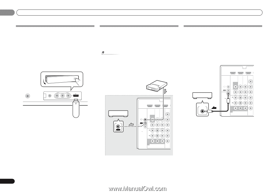
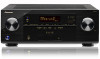
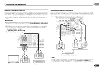
02 Connecting your equipment Connecting a USB device It is possible to listen to two-channel audio using the USB interface on the front of this receiver. Switch the receiver into standby then connect your USB device to the USB terminal on the front panel of this receiver. • Push down on the PUSH OPEN tab to access the USB terminal. • This receiver does not support a USB hub. • For instructions on playing the USB device, see Playing a USB device on page 28. CONTROL ON / OFF PHONES This receiver MCACC SETUP MIC VIDEO 2 INPUT 5V 2.1 A L AUDIO R iPod iPhone USB VIDEO iPad USB mass storage device Connecting an IR receiver If you keep your stereo components in a closed cabinet or shelving unit, or you wish to use the sub zone remote control in another zone, you can use an optional IR receiver (such as a Niles or Xantech unit) to control your system instead of the remote sensor on the front panel of this receiver. Note • Remote operation may not be possible if direct light from a strong fluorescent lamp is shining on the IR receiver remote sensor window. • Note that other manufacturers may not use the IR terminology. Refer to the manual that came with your component to check for IR compatibility. IR receiver HDMI DVR/BDR IN DVD IN BD IN V Other component IR IN IR IN OUT 12 V TRIGGER (OUTPUT 12 V 50 mA MAX) VIDEO AUDIO DVR/BDR C MONITOR TV/SAT BD OUT IN IN OUT DVR/ BDR OUT IN 1 (DVD) ASSIGN ABLE IN 2 (DVR/ BDR) IN DVD IN IN IN Closet or shelving unit MONITOR OUT Y PB PR COMPONENT VIDEO TV/SAT Switching components on and off using the 12 volt trigger You can connect components in your system (such as a screen or projector) to this receiver so that they switch on or off using 12 volt triggers when you select an input function. However, you must specify which input functions switch on the trigger using the The 12 V Trigger Setting on page 42. Note that this will only work with components that have a standby mode. HDMI DVR/BDR IN DVD IN BD IN V 12 V TRIGGER INPUT IR IN OUT 12 V TRIGGER (OUTPUT 12 V 50 mA MAX) VIDEO AUDIO DVR/BDR C MONITOR TV/SAT BD OUT IN IN OUT DVR/ BDR OUT IN 1 (DVD) ASSIGN ABLE IN 2 (DVR/ BDR) IN DVD IN IN IN MONITOR OUT Y PB PR COMPONENT VIDEO TV/SAT Connect the 12 V TRIGGER jack of this receiver to the 12 V trigger of another component. Use a cable with a mono mini-plug on each end for the connection. After you've specified the input functions that will switch on the trigger, you'll be able to switch the component on or off just by pressing the input function(s) you've set on page 42. Connect the IR receiver sensor to the IR IN jack on the rear of this receiver. For more information on connecting the IR receiver, see the Installation Instructions for the IR Receiver. 22 En
-
 1
1 -
2
-
3
-
4
-
5
-
6
-
7
-
8
-
9
-
10
-
11
-
12
-
13
-
14
-
15
-
16
-
 17
17 -
 18
18 -
 19
19 -
 20
20 -
 21
21 -
 22
22 -
 23
23 -
 24
24 -
 25
25 -
 26
26 -
 27
27 -
28
-
29
-
30
-
31
-
32
-
33
-
34
-
35
-
36
-
37
-
38
-
39
-
40
-
41
-
42
-
43
-
44
-
45
-
46
-
47
-
48
-
49
-
50
-
51
-
52
-
53
-
54
-
55
-
56
 |
 |